background image

Chapter 5 Detailed Descriptions of I/O Modules


GFK-2958E 

RSTi-EP User Manual 

148


Process

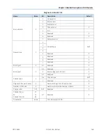
 Data Inputs EP-225F  

Byte 

Bit 

Description 

OB0 

OX0.0 

DO0 

OX0.1 

DO1 

OX0.2 

DO2 

OX0.3 

DO3 

OX0.4 

DO4 

OX0.5 

DO5 

OX0.6 

DO6 

OX0.7 

DO7 

OB1 

OX1.0 

DO8 

OX1.1


DO9 

OX1.2


DO10 

OX1.3


DO11


OX1.4


DO12


OX1.5


DOI13


OX1.6


DO14


OX1.7


DO15


Internal process data mapping with data format “Standard”. Depending on

 the fieldbus specification and the data 

format of the communicating fieldbus components the bytes and/or words can be reversed during data transfer. 


Summary of Contents for RSTi-EP

Page 1: ...RSTi EP User Manual GFK 2958E November 2017...

Page 2: ...f at any time This document is intended for trained personnel familiar with the GE products referenced herein Public This document is approved for public disclosure GE may have patents or pending pate...

Page 3: ...observed could result in personal injury or death Caution Indicates a procedure or condition that if not strictly observed could result in damage to or destruction of equipment Attention Indicates a p...

Page 4: ...ll free 800 option is unavailable Technical Support Email support ip ge com Customer Care Email customercare ip ge com Primary language of support English Europe the Middle East and Africa Online Tech...

Page 5: ...Electrostatic Discharge 20 2 1 2 Open Equipment 20 2 1 3 Fusing 21 2 1 4 Earthing functional earth FE 21 2 1 5 Shielding 21 2 1 6 Overcurrent 21 2 2 INTENDED USE 21 2 3 USE IN A POTENTIALLY EXPLOSIVE...

Page 6: ...3 5 Module Status Messages 74 4 3 6 Module Diagnosis 74 4 3 7 Supported Modules and Power Supplies 75 4 4 MODBUS TCP NETWORK ADAPTER EPXMBE001 EPXMBE101 76 4 4 1 LEDs 77 4 4 2 Connection Diagrams 79...

Page 7: ...INPUT MODULE EP 125F 111 5 6 DIGITAL INPUT MODULE EP 12F4 116 5 6 1 Time Stamp Function 120 5 6 2 Structure of an ETS Entry 120 5 6 3 Example for the Mode of Operation 121 5 7 DIGITAL OUTPUT MODULE E...

Page 8: ...10 310 5 39 TERMINATION KIT EP 8301 311 6 1 PREPARATIONS FOR ASSEMBLY 313 6 1 1 Environmental Conditions 313 6 1 2 DIN Rail 313 6 1 3 Stripping Lengths 313 6 1 4 Unpacking and Delivery 314 6 1 5 Use i...

Page 9: ...vice Drivers 361 9 2 INSTALLING THE USB DRIVER 361 9 3 STARTING THE WEB SERVER 362 9 3 1 Activating the Ethernet Socket 363 9 4 SETTING UP REGISTRATION DATA AND PASSWORD PROTECTION 364 9 5 NAVIGATION...

Page 10: ...4 REMOVING REPLACING CONNECTORS 391 10 5 REMOVING REPLACING CABLES 393 11 1 DISASSEMBLING THE RSTI EP STATION 395 11 2 DISPOSING OF THE RSTI EP STATION 396 12 1 FIELDBUS NETWORK ADAPTERS 398 12 2 I O...

Page 11: ...provides detailed descriptions of the network adapters Chapter 5 provides detailed descriptions of the I O modules Chapter 6 provides information on installation and setup Chapter 7 provides informat...

Page 12: ...mponents belong to the RSTi EP product series Fieldbus network adapter gateway Head station for converting the respective fieldbus protocol on the RSTi EP system bus Active I O modules o Modules with...

Page 13: ...99 in End bracket 120 0 mm 4 72 in 8 0 mm 0 32 in 36 0 mm 1 42 in 1 2 1 Double click Installation The RSTi EP station modules can be installed quickly and simply When attaching the module to the DIN...

Page 14: ...Chapter 4 Detailed Descriptions of the Fieldbus Network Adapter Fieldbus Network Adapter example EPXPNS001 1 Catch lever for securing the DIN rail 2 Rotary switch only PROFIBUS 3 Data line connection...

Page 15: ...ge transport 95 non condensing as per IEC 61131 2 Air pressure Operation 795 hPa altitude 2000 m as per IEC 61131 2 Storage transport 700 hPa altitude 3000 m as per IEC 61131 2 Vibration resistance 5...

Page 16: ...User Manual 12 Unless otherwise noted within the product specific technical data All product specific technical data is available in the corresponding product description in Chapter 4 Detailed Descri...

Page 17: ...ice 10 Module status LED collective message 11 Connector 12 Channel status LEDs 13 Latching hook for latching onto module sides 14 DIN rail foot 15 Type plate I O Module Components Color Coding The re...

Page 18: ...efer to the section Wiring Connector with Four Conductor Connectors Features and Specifications conductor cross section 0 14 to 1 5 mm AWG 16 26 maximum ampacity 10 A 4 pole The pushers are color code...

Page 19: ...EP 2614 Digital Output 4 Points Positive Negative Logic 24VDC 2 0A 2 3 or 4 Wire EP 2634 Analog input modules Analog Input 4 Channels Voltage Current 16 Bits 2 3 or 4 Wire EP 3164 Analog Input 4 Chan...

Page 20: ...6 8 4 Hz f 150 Hz 1 g acceleration as per IEC 60068 2 6 Shock resistance 15 g over 11 ms half sinewave as per IEC 60068 2 27 Potential isolation Test voltage max 28 8 V within one channel 500 V DC fie...

Page 21: ...ination kit with end plate and end bracket right end For vertical installation a special end bracket must also be installed below the station 1 8 Type Plate Each network adapter and each module featur...

Page 22: ...pment 1 9 1 Swivel Marker RSTi EP I O Label Markers EP 8100 allow for modules and all respective channels and lines to be labelled in detail They are attached to the connector frame Module with Swivel...

Page 23: ...Chapter 1 Introduction GFK 2958E RSTi EP User Manual 19 Notes...

Page 24: ...technical help contact Technical Support For phone numbers and email addresses refer to the General Contact Information page in the front of this manual If a malfunction on a RSTi EP product cannot be...

Page 25: ...fully in accordance with the instructions refer to Chapter 6 Installation The module is earthed by connecting the DIN rail to the protective earth via the earth terminal Modules EP 700F EP 1214 EP 221...

Page 26: ...stabilized 24V DC power supply with double or reinforced insulation shall be used When using modules EP 2714 EP 2814 and EP 1804 in explosive atmosphere o Device shall be installed in an environment f...

Page 27: ...c DEMKO 16 ATEX 1591X Ex nA nC IIC T4 Gc IECEx ULD 16 0022X Ta 20 C to 60 C 2 4 Legal Notice The RSTi EP series products are CE compliant in accordance with Directive 2014 30 EU EMC Directive and Dire...

Page 28: ...including max 64 active modules can be aligned on a network adapter The RSTi EP station is usually installed on a horizontally positioned DIN rail Installation Position of the RSTi EP Station on the...

Page 29: ...ution module power feed module or blank module may be placed in successive positions Then at least one active module must follow 3 1 1 Arrangement of Safe Power feed Modules A safe power feed module E...

Page 30: ...t demand refer to the sections Example Calculation for the Power Supply and Calculation of Power Loss of this manual 3 2 Installation Distances In order to be able to carry out the installation and su...

Page 31: ...Configuration GFK 2958E RSTi EP User Manual 27 Minimum Distances for Horizontal Installation Minimum Distances for Vertical Installation Minimum Distance for Electrical Cabinet Door Without With Swiv...

Page 32: ...etwork adapter n modules end plate and end bracket distances to the sides For vertical installation interchange height and width When calculating the width 4 5 mm 0 18 in for the must be added for the...

Page 33: ...64 active modules without having to refresh the power The IIN input current path supplies the input circuit of the input modules as well as the connected IS sensors The current must be refreshed with...

Page 34: ...odules EP 3164 EP 3124 EP 3264 8 mA 25 mA x EP 3804 EP 3704 EP 3368 EP 3468 8 mA 20 mA Analog output modules EP 4164 EP 4264 8 mA 85 mA Functional modules EP 5111 EP 5112 8 mA 35 mA x EP 5212 8 mA 35...

Page 35: ...ge need not be considered during this step Note Use the RSTi EP Power Supply Configuration Guide to perform this calculation automatically 3 6 1 Calculation of the Current Demand for the Input Current...

Page 36: ...08 A 0 012 A 0 06 A x 1 0 196 A Module 2 I 0 196 A 0 008 A 0 012 A 0 06 A x 1 0 276 A The values for the other modules are calculated accordingly The result shows that the accumulated value for up to...

Page 37: ...EP 2218 0 008 0 035 4 0 5 0 656 3 07 7 EP 2218 0 008 0 035 3 0 5 0 664 4 605 8 EP 2218 0 008 0 035 2 0 5 0 672 5 64 9 EP 2218 0 008 0 035 1 2 0 5 0 68 6 275 10 EP 2218 0 008 0 035 4 0 5 0 688 8 29 EP...

Page 38: ...oss of 2 watts for the module Maximum values were assumed for these calculations If you need detailed calculations please contact GE technical support or GlobalCare Pstation Pnetwork adapter N Pmodule...

Page 39: ...Ii P Feedback energy of the module Ni Switching cycles of Channel i in 1 seconds Ei Feedback energy when shutting off Channel i during a shutdown procedure Ii Current through the load connected to Ch...

Page 40: ...1 in V0 they are inactive Diagnostic messages are generated which are acknowledged by the PLC Identifier related diagnosis enabled disabled enabled Channel related diagnosis enabled disabled enabled M...

Page 41: ...oduct Part No Parameter Optional values Default value Modbus TCP Network Adapter 2 Cu RJ45 Ports 2048 bytes Input Output EPXMBE001 EPXMBE101 IP Address In Dual LAN Mode EPXMBE101 only parameterizable...

Page 42: ...tinue data exchange Behavior like fieldbus error Continue data exchange see register 0x1136 Data format Motorola Intel Motorola see fieldbus register 0x1137 Product Part No Parameter Optional values D...

Page 43: ...nts Positive Logic 24VDC 0 5A 2 Wire EP 2218 Ch 0 Ch 7 Substitute value Off 0 On 1 Off Product Part No Parameter Optional values Default value Digital Output 4 Points Positive Logic 230 VAC 0 5A Digit...

Page 44: ...h 0 Process alarm end value disabled 0 enabled 1 disabled Ch 0 Process alarm latch value disabled 0 enabled 1 disabled Ch 0 Counting mode count endless 0 once forward 1 once backwards 2 once no main d...

Page 45: ...ignal A 0 01 ms 100 kHz 0 0 017 ms 50 kHz 1 0 033 ms 30 kHz 2 0 1 ms 10 kHz 3 0 2 ms 5 kHz 4 0 5 ms 2 kHz 5 1 ms 1 kHz 6 0 01 ms Ch 0 Ch 1 Filter time signal B 0 01 ms 100 kHz 0 0 017 ms 50 kHz 1 0 03...

Page 46: ...48 2147483647 0 Ch 0 Ch 1 Hysteresis 0 255 0 Product Part No Parameter Optional values Default value 2 Channel Frequency Measurement 100 kHz EP 5212 Ch 0 Ch 1 Input filter 5 s 187 kHz 0 11 s 94 kHz 1...

Page 47: ...sabled 8 disabled Product Part No Parameter Optional values Default value Analog Input 8 Channels Current 16 Bits 2 3 or 4 Wire EP 3368 Frequency suppression disabled 0 50 Hz 1 60 Hz 2 Average over 16...

Page 48: ...Ch 0 Ch 3 Channel diagnosis disabled 0 enabled 1 disabled Product Part No Parameter Optional values Default value Analog Input 4 Channels RTD 16 Bits with Diagnostics 2 3 or 4 Wire EP 3704 Temperatur...

Page 49: ...fault value Analog Input 4 Channels TC 16 Bits with Diagnostics 2 3 or 4 Wire EP 3804 Temperature unit Degree Celsius 0 Degree Fahrenheit 1 Kelvin 2 Degree Celsius Ch 0 Ch 3 Measurement range TC Type...

Page 50: ...Chapter 3 Configuration GFK 2958E RSTi EP User Manual 46 Ch 0 Ch 3 Limit value monitoring disabled 0 enabled 1 disabled Ch 0 Ch 3 High limit value 32768 32767 0 Ch 0 Ch 3 Low limit value 32768 32767 0...

Page 51: ...Output 4 Points Positive Logic 24VDC 0 5A 2 3 or 4 Wire 3 4 47 1 EP 2614 Digital Output 4 Points Positive Logic 24VDC 2 0A 2 3 or 4 Wire 3 4 47 1 EP 2634 Digital Output 4 Points Positive Negative Logi...

Page 52: ...h Diagnostics 2 3 or 4 Wire 3 31 47 8 EP 3368 Analog Input 8 Channels Current 16 Bits 2 3 or 4 Wire 3 13 47 16 EP 3468 Analog Input 8 Channels Current 16 Bits 2 3 or 4 Wire Channel Diagnostic 3 13 47...

Page 53: ...t 4 Points Positive Logic 24VDC 2 0A 2 3 or 4 Wire 4 5 47 1 2 EP 2634 Digital Output 4 Points Positive Negative Logic 24VDC 2 0A 2 3 or 4 Wire 4 5 47 1 2 EP 2218 Digital Output 8 Points Positive Logic...

Page 54: ...VDC Programmable Delay 4 47 5 1 EP 1902 2 Safe Feed Inputs 24 VDC 4 47 5 1 Max data in bytes 260 4362 1408 512 512 EPXETC001 Part No Module Configuration Parameter Diagnostics Process data Bytes Bytes...

Page 55: ...4VDC 2 A 4 8 47 4 12 EP 3164 Analog Input 4 Channels Voltage Current 16 Bits 2 3 or 4 Wire 4 6 47 8 EP 3264 Analog Input 4 Channels Voltage Current 16 Bits with Diagnostics 2 3 or 4 Wire 4 8 47 8 EP 3...

Page 56: ...Chapter 3 Configuration GFK 2958E RSTi EP User Manual 52 Notes...

Page 57: ...ed The PROFIBUS DP network adapter has a Sub D socket and supports all services in accordance with the DP V1 specification The network adapter can be accessed with a system independent web server appl...

Page 58: ...onnected SF System fault Red Configuration error or error in the network adapter or error in a module or there is a new diagnostic report Red flashing Station in Force mode BF Bus fault Red No connect...

Page 59: ...At least one current path 18 V 3 1 Green Input current path supply voltage 18 V DC 3 2 Red Input current path supply voltage 18 V DC 3 3 3 4 Red Internal fuse defective 4 1 Green Output current path s...

Page 60: ...ally used by the control systems Bus addresses 000 plus 126 and higher may not be used The most significant digit is set with rotary switch H the least significant digit with rotary switch L The switc...

Page 61: ...er 4 Detailed Descriptions of the Fieldbus Network Adapters GFK 2958E RSTi EP User Manual 57 4 1 3 Connection Diagrams Door for Micro USB Port Connection Diagram EPXPBS001 EPXPBS001 Block Diagram EPXP...

Page 62: ...ltage for outputs 20 4V 28 8V Max feed in current for input modules 10 A Max feed in current for output modules 10 A Current consumption from system current path ISYS 100 mA Connection data Type of co...

Page 63: ...gers are set in the engineering environment Diagnostic alarm These switches can be selected only in mode V1 in V0 they are inactive Diagnostic messages are generated which are acknowledged by the PLC...

Page 64: ...ut Modules EP 3164 Analog Input 4 Channels Voltage Current 16 Bits 2 3 or 4 Wire EP 3264 Analog Input 4 Channels Voltage Current 16 Bits with Diagnostics 2 3 or 4 Wire EP 3124 Analog Input 4 Channels...

Page 65: ...ntial Distribution 24 VDC from Input Current Path EP 751F Power Module 16 Channels 24VDC Potential Distribution 24 VDC from Output Current Path EP 700F Power Module 16 Channels 24VDC Potential Distrib...

Page 66: ...OFINET network adapter has two Ethernet ports and an integrated switch The PROFINET Scanner can be accessed with a system independent web server application via the USB service interface or the Ethern...

Page 67: ...1 Connection Green Connection established between port 1 of the PROFINET Scanner and another field device ACT 1 Active Yellow flashing Data being exchanged on port 1 LINK 2 Connection Green Connectio...

Page 68: ...STi EP User Manual 64 4 2 2 Connection Diagrams Door for Micro USB Port Connection Diagram EXPNS001 Caution In the case of a maximum power supply of 8 A and a maximum temperature of 55 C all four cont...

Page 69: ...s Supports MRP Yes Supply Supply voltage for system and inputs 20 4V 28 8V Supply voltage for outputs 20 4V 28 8V Max feed in current for input modules 10 A Max feed in current for output modules 10 A...

Page 70: ...locked Force mode unlocked Change requires restart of the network adapter 4 2 4 Supported Modules and Power Supplies The following modules can be used with this release of the RSTi EP PROFINET Networ...

Page 71: ...High Speed Counter AB 100 kHz EP 5212 2 Channel Frequency Measurement 100 kHz EP 5261 1 Channel Serial Communications 232 422 485 EP 5311 1 Channel SSI Encoder BCD or Gray Code Format 5 24 VDC EP 542...

Page 72: ...hernet ports and an integrated switch The network adapter can be accessed with a system independent web server application via the USB service interface or the EtherCAT Thus all information such as di...

Page 73: ...Maintenance Required Yellow Error on the system bus or fieldbus L A IN Connection Activity Green Connection established between port 1 of the network adapter and another field device Green flashing D...

Page 74: ...t current path supply voltage 18 V DC 3 2 Red Input current path supply voltage 18 V DC 3 3 3 4 Red Internal fuse defective 4 1 Green Output current path supply voltage 18 V DC 4 2 Red Output current...

Page 75: ...ieldbus Network Adapters GFK 2958E RSTi EP User Manual 71 Caution In the case of a maximum power supply of 8 A and a maximum temperature of 55 C 131 F all four contacts must be connected with 1 5 mm w...

Page 76: ...85 C 40 F to 185 F Air humidity operation transport 5 to 95 noncondensing as per IEC 61131 2 Width 52 mm 2 05 in Depth 76 mm 2 99 in Height 120 mm 4 72 in Weight 227 g 8 oz Configuration ESI file is a...

Page 77: ...ation error Deviation in the configuration The module list has changed The list of configured modules Configured Module Ident List 0xF030 differs from the module list detected by the network adapter D...

Page 78: ...in an EPXETC001 Station Status value Meaning 0x0 Plug in station is undefined 0x1 Plug in station module OK 0x80 Plug in station empty module has been removed 0x81 Incorrect module plugged in 4 3 6 Mo...

Page 79: ...t 8 Channels Current 16 Bits 2 3 or 4 Wire EP 3468 Analog Input 8 Channels Current 16 Bits 2 3 or 4 Wire Channel Diagnostic EP 3704 Analog Input 4 Channels RTD 16 Bits with Diagnostics 2 3 or 4 Wire E...

Page 80: ...or this purpose the EPXMBE101 has two MAC addresses and two IP addresses that can be defined separately over two different LAN networks The Modbus Dual LAN mode is suitable to communicate with two syn...

Page 81: ...Chapter 4 Detailed Descriptions of the Fieldbus Network Adapters GFK 2958E RSTi EP User Manual 77 4 4 1 LEDs LED Status Indicators EPXMBE001 EPXMBE101...

Page 82: ...tablished between port 1 of the network adapter and another field device Green flashing Yellow flashing Data being exchanged on port 1 L A X2 Connection Active Green Connection established between por...

Page 83: ...anual 79 4 4 2 Connection Diagrams Door for Micro USB Port Connection Diagram EPXMBE001 EPXMBE101 Caution In the case of a maximum power supply of 8 A and a maximum temperature of 55 C 131 F all four...

Page 84: ...ax 48 Mbps Supply Supply voltage for system and inputs 20 4V 28 8V Supply voltage for outputs 20 4V 28 8V Max feed in current for input modules 10 A Max feed in current for output modules 10 A Current...

Page 85: ...egister 0x1120 MODBUS DATA EXCHANGE watchdog predefined time Modbus Connection Timeout Connection watchdog time in sec 1 s refer to register 0x1131 MODBUS CONNECTION Timeout in Sec Write access in mul...

Page 86: ...etwork adapter status Bit assignment as with EPXETC001 0x1010 ro Word Process image length in bits for the output modules 0x1011 ro Word Process image length in bits for the input modules 0x1017 ro Wo...

Page 87: ...00 0x2A7F ro Long Current module list max 64 modules per station 2 registers per module There must always be 2 4 6 etc registers transferred 0x8000 0x87FF ro Module Process data inputs max 64 modules...

Page 88: ...4 Points 110 230 VAC 65 277 VAC 2 Wire Isolated Digital Output Modules EP 2214 Digital Output 4 Points Positive Logic 24VDC 0 5A 2 3 or 4 Wire EP 2614 Digital Output 4 Points Positive Logic 24VDC 2 0...

Page 89: ...Access to all 512 registers is always possible regardless of the I O structure Unused registers respond with 0 Packed output process data Output register range 0x0800 to 0x09FF Note Access to all 512...

Page 90: ...te 1 0 allocated 1 register EP 125F 2 Byte 1 allocated 1 register Total 7 4 Data Widths of I O Modules in the Modbus Register Range Module Process data Input Output EP 1214 1 Byte EP 1218 1 Byte EP 13...

Page 91: ...hapter 4 Detailed Descriptions of the Fieldbus Network Adapters GFK 2958E RSTi EP User Manual 87 EP 3468 8 Word EP 4164 4 Word EP 4264 4 Word EP 3704 4 Word EP 1901 4 Byte EP 1922 4 Byte EP 1902 4 Byt...

Page 92: ...he modules 8 Errorbit 8 Reserve bit 8 currently not used 9 Errorbit 9 Reserve bit 9 currently not used 10 Force mode active Force mode was activated via the web server Forced channels do not exchange...

Page 93: ...data missing module 4 4 140x1030 MODBUS DATA EXCHANGE Watchdog Current Time Amount of time input value 10 ms still remaining on the active watchdog to monitor the exchange of process data If a 0 is re...

Page 94: ...ng the reference module list 0x2800 and the following against the current module list 0x2A00 and the following The reference module list must also not be described If the value in in register 0x1132 i...

Page 95: ...079 076 069 086 065 083 ASCII hexadecimal 44 41 4F 4C 45 56 41 53 Input in register no 0x113C 0x113D 0x113E 0x113F Hexadecimal 4441 4F4C 4556 4153 Decimal 17473 20300 17750 16723 The not editable par...

Page 96: ...n register 0x1134 reading out the corresponding diagnosis results in a confirmation of the alarm 4 4 350xB000 0xB7FF Process Alarms For each module a process alarm data length of 64 bytes 32 registers...

Page 97: ...s 5 1 Digital Input Module EP 1214 Digital Input Module EP 1214 Connection Diagram EP 1214 The digital input module EP 1214 can detect up to 4 input signals One sensor can be connected to each connect...

Page 98: ...e system bus Red Module System Fault or Diagnostic Fault 1 1 Yellow Input 0 active 1 2 1 3 1 4 2 1 Yellow Input 1 active 2 2 2 3 2 4 3 1 Yellow Input 2 active 3 2 3 3 3 4 4 1 Yellow Input 3 active 4 2...

Page 99: ...20 ms Off voltage 5 V On voltage 11 V Sensor supply max 2 A per plug total max 8 A Sensor connection 2 wire 3 wire 3 wire FE Reverse polarity protection Yes Module diagnosis Yes Individual channel dia...

Page 100: ...dule Type 0x0F 1 2 3 4 Reserved 0 5 Reserved 0 6 Reserved 0 7 Reserved 0 Error byte 2 2 0 7 Reserved 0 Error byte 3 3 0 2 Reserved 0 3 Internal diagnostic FIFO full 0 4 7 Reserved 0 Channel type 4 0 6...

Page 101: ...rved IX0 6 reserved IX0 7 reserved 5 2 Digital Input Module EP 1218 Digital Input Module EP 1218 Connection Diagram EP 1218 The digital input module EP 1218 can detect up to 8 input signals Two sensor...

Page 102: ...agnostic Fault 1 1 Yellow Input 0 active 1 2 1 3 Yellow Input 1 active 1 4 2 1 Yellow Input 2 active 2 2 2 3 Yellow Input 3 active 2 4 3 1 Yellow Input 4 active 3 2 3 3 Yellow Input 5 active 3 4 4 1 Y...

Page 103: ...to 20 ms Low input voltage 5 V High input voltage 11 V Sensor supply max 15 mA per channel Sensor connection 2 wire Reverse polarity protection Yes Module diagnosis Yes Individual channel diagnosis N...

Page 104: ...odule Type 0x0F 1 2 3 4 Reserved 0 5 Reserved 0 6 Reserved 0 7 Reserved 0 Error byte 2 2 0 7 Reserved 0 Error byte 3 3 0 2 Reserved 0 3 Internal diagnostic FIFO full 0 4 7 Reserved 0 Channel type 4 0...

Page 105: ...IX0 6 DI6 IX0 7 DI7 5 3 Digital Input Module EP 1318 Digital Input Module EP 1318 Connection Diagram EP 1318 The digital input module EP 1318 can detect up to 8 input signals Two sensors can be connec...

Page 106: ...em Fault or Diagnostic Fault 1 1 Yellow Input 0 active 1 2 1 3 1 4 Yellow Input 1 active 2 1 Yellow Input 2 active 2 2 2 3 2 4 Yellow Input 3 active 3 1 Yellow Input 4 active 3 2 3 3 3 4 Yellow Input...

Page 107: ...ms Low input voltage 5 V High input voltage 11 V Sensor supply max 2 A per plug total max 8 A Sensor connection 2 wire 3 wire Reverse polarity protection Yes Module diagnosis Yes Individual channel di...

Page 108: ...rved 0 Error byte 2 2 0 7 Reserved 0 Error byte 3 3 0 2 Reserved 0 3 Internal diagnostic FIFO full 0 4 7 Reserved 0 Channel type 4 0 6 Channel type 0x70 7 Reserved 0 Diagnostic bits per channel 5 Numb...

Page 109: ...agram EP 1804 The digital input module EP 1804 can detect up to 4 binary control signals One sensor can be connected to each connector using a 2 wire connection Both L and N connections of each input...

Page 110: ...nal lines must be supplied from the same power system Attention The module can be destroyed by too high frequencies The input frequency may be 65 Hz at maximum the switching frequency 15 Hz at maximum...

Page 111: ...en Communication over the system bus Red Module System Fault or Diagnostic Fault 1 1 Yellow Input 0 active 1 2 1 3 1 4 2 1 Yellow Input 1 active 2 2 2 3 2 4 3 1 Yellow Input 2 active 3 2 3 3 3 4 4 1 Y...

Page 112: ...etween channels and power supply Line to line voltage 400V between the channels possible Inputs Number 4 Input type P switching for Type 3 sensors as per IEC 61131 2 Input filter Input delay 10 ms Low...

Page 113: ...x05 1 2 3 4 Reserved 0 5 Reserved 0 6 Reserved 0 7 Reserved 0 Error byte 2 2 0 7 Reserved 0 Error byte 3 3 0 2 Reserved 0 3 Internal diagnostic FIFO full 0 4 Power supply fault 0 5 7 Reserved 0 Channe...

Page 114: ...d Descriptions of I O Modules GFK 2958E RSTi EP User Manual 110 Process Data Inputs EP 1804 Byte Bit Description IB0 IX0 0 DI0 IX0 1 DI1 IX0 2 DI2 IX0 3 DI3 IX0 4 Reserved IX0 5 Reserved IX0 6 Reserve...

Page 115: ...EP 125F Connection Diagram EP 125F The EP 125F digital input module can detect up to 16 input signals Four sensors can be connected to each connector in a 1 wire connection A status LED is assigned to...

Page 116: ...2 active 1 4 Yellow Input 3 active 2 1 Yellow Input 4 active 2 2 Yellow Input 5 active 2 3 Yellow Input 6 active 2 4 Yellow Input 7 active 3 1 Yellow Input 8 active 3 2 Yellow Input 9 active 3 3 Yell...

Page 117: ...on bus System bus transfer rate 48 Mbps Inputs Number 16 Sensor types Type 1 and Type 3 sensors as per IEC 61131 2 Input filter Input delay 3 ms Low input voltage 5 V High input voltage 11 V Sensor su...

Page 118: ...odule Type 0x0F 1 2 3 4 Reserved 0 5 Reserved 0 6 Reserved 0 7 Reserved 0 Error byte 2 2 0 7 Reserved 0 Error byte 3 3 0 2 Reserved 0 3 Internal diagnostic FIFO full 0 4 7 Reserved 0 Channel type 4 0...

Page 119: ...DI2 IX0 3 DI3 IX0 4 DI4 IX0 5 DI5 IX0 6 DI6 IX0 7 DI7 IB1 IX1 0 DI8 IX1 1 DI9 IX1 2 DI10 IX1 3 DI11 IX1 4 DI12 IX1 5 DI13 IX1 6 DI14 IX1 7 DI15 Internal process data mapping with data format Standard...

Page 120: ...EP 12F4 can detect up to 4 binary control signals and provide them with a time stamp resolution 1 s Depending on the configuration of the module up to 5 or 15 time stamp entries can be evaluated One...

Page 121: ...No communication on system bus or there is a diagnostic message displayed 1 1 Yellow Input 0 active 1 2 1 3 1 4 2 1 Yellow Input 1 active 2 2 2 3 2 4 3 1 Yellow Input 2 active 3 2 3 3 3 4 4 1 Yellow I...

Page 122: ...upply Yes Sensor connection 2 wire 3 wire 3 wire FE Reverse polarity protection Yes Module diagnosis Yes Individual channel diagnosis No Time stamp data width 16 bits Time stamp resolution 1 s Supply...

Page 123: ...odule Type 0x0F 1 2 3 4 Reserved 0 5 Reserved 0 6 Reserved 0 7 Reserved 0 Error byte 2 2 0 7 Reserved 0 Error byte 3 3 0 2 Reserved 0 3 Internal diagnostic FIFO full 0 4 7 Reserved 0 Channel type 4 0...

Page 124: ...ed during data transfer 5 6 1 Time Stamp Function With time stamp function ETS edge time stamp enabled at every corresponding edge the time value of the timer is stored in the process image as an ETS...

Page 125: ...are predefined as follows DI 0 and DI 1 time stamp at edge 0 1 enabled DI 2 and DI 3 time stamp at edge 0 1 disabled DI 0 and DI 1 time stamp at edge 1 0 enabled DI 2 and DI 3 time stamp at edge 1 0 d...

Page 126: ...ETS Entry at t2 A rising 0 1 edge on DI 1 causes the 2nd ETS entry at address 0 The 1st ETS entry is shifted by 4 bytes 3rd ETS Entry at t3 A falling 1 0 edge on DI 0 causes the 3rd ETS entry 4th to14...

Page 127: ...Manual 123 16th ETS Entry at t16 A rising 0 1 edge on DI 1 causes the16th ETS entry The 1st ETS entry is deleted and not available anymore 17th ETS Entry at t17 A falling 1 0 edge on DI 1 causes the1...

Page 128: ...14 Connection Diagram EP 2214 The EP 2214 digital output module can control up to 4 discrete outputs each with a maximum of 0 5 A One discrete output can be connected to each connector using a 2 wire...

Page 129: ...system bus Red Module System Fault or Diagnostic Fault 1 1 Yellow Output 0 active 1 2 1 3 1 4 2 1 Yellow Output 1 active 2 2 2 3 2 4 3 1 Yellow Output 2 active 3 2 3 3 3 4 4 1 Yellow Output 3 active 4...

Page 130: ...esistive load min 47 1 kHz Inductive load DC 13 0 2 Hz without free wheeling diode 1 kHz with suitable free wheeling diode Lamp load 12 W 1 kHz Actuator connection 2 wire 3 wire 3 wire FE Actuator sup...

Page 131: ...served 0 6 Reserved 0 7 Parameter error Module type 1 0 Module Type 0x0F 1 2 3 4 Reserved 0 5 Reserved 0 6 Reserved 0 7 Reserved 0 Error byte 2 2 0 7 Reserved 0 Error byte 3 3 0 2 Reserved 0 3 Interna...

Page 132: ...d Descriptions of I O Modules GFK 2958E RSTi EP User Manual 128 Process Data Outputs EP 2214 Byte Bit Description OB0 OX0 0 DO0 OX0 1 DO1 OX0 2 DO2 OX0 3 DO3 OX0 4 reserved OX0 5 reserved OX0 6 reserv...

Page 133: ...614 Connection Diagram EP 2614 The digital output module EP 2614 can control up to 4 discrete outputs each with a maximum of 2 A One discrete output can be connected to each connector using a 2 wire 3...

Page 134: ...cation over the system bus Red Module System Fault or Diagnostic Fault 1 1 Yellow Output 0 active 1 2 1 3 1 4 2 1 Yellow Output 1 active 2 2 2 3 2 4 3 1 Yellow Output 2 active 3 2 3 3 3 4 4 1 Yellow O...

Page 135: ...Hz without free wheeling diode 1 kHz with suitable free wheeling diode Lamp load 12 W 1 kHz Actuator connection 2 wire 3 wire 3 wire FE Actuator supply max 2 A per plug total max 8 A Short circuit pro...

Page 136: ...odule Type 0x0F 1 2 3 4 Reserved 0 5 Reserved 0 6 Reserved 0 7 Reserved 0 Error byte 2 2 0 7 Reserved 0 Error byte 3 3 0 2 Reserved 0 3 Internal diagnostic FIFO full 0 4 7 Reserved 0 Channel type 4 0...

Page 137: ...d Descriptions of I O Modules GFK 2958E RSTi EP User Manual 133 Process Data Outputs EP 2614 Byte Bit Description OB0 OX0 0 DO0 OX0 1 DO1 OX0 2 DO2 OX0 3 DO3 OX0 4 reserved OX0 5 reserved OX0 6 reserv...

Page 138: ...ng This allows among other things a switch in rotational direction if an DC motor is connected between two outputs For this purpose an output byte is reserved for the physical outputs and each channel...

Page 139: ...cation over the system bus Red Module System Fault or Diagnostic Fault 1 1 Yellow Output 0 active 1 2 1 3 1 4 2 1 Yellow Output 1 active 2 2 2 3 2 4 3 1 Yellow Output 2 active 3 2 3 3 3 4 4 1 Yellow O...

Page 140: ...sistive load min 47 1 kHz Inductive load DC 13 0 2 Hz without free wheeling diode 1 kHz with suitable free wheeling diode Lamp load 12 W 1 kHz Actuator connection 2 wire 3 wire 3 wire FE Actuator supp...

Page 141: ...3 Channel error 0 4 Error 5 Reserved 0 6 Reserved 0 7 Parameter error Module type 1 0 Module Type 0x0F 1 2 3 4 Reserved 0 5 Reserved 0 6 Reserved 0 7 Reserved 0 Error byte 2 2 0 7 Reserved 0 Error byt...

Page 142: ...er Manual 138 Process Data Outputs EP 2634 Byte Format Name Remark OB0 OX0 0 OP mode DO0 0 Sinking 1 Sourcing OX0 1 OP mode DO1 0 Sinking 1 Sourcing OX0 2 OP mode DO2 0 Sinking 1 Sourcing OX0 3 OP mod...

Page 143: ...t Module EP 2218 Connection Diagram EP 2218 The EP 2218 digital output module can control up to 8 discrete outputs each with a maximum of 0 5A Discrete outputs can be connected to each connector in a...

Page 144: ...tic Fault 1 1 Yellow Output 0 active 1 2 1 3 Yellow Output 1 active 1 4 2 1 Yellow Output 2 active 2 2 2 3 Yellow Output 3 active 2 4 3 1 Yellow Output 4 active 3 2 3 3 Yellow Output 5 active 3 4 4 1...

Page 145: ...d min 47 1 kHz Inductive load DC 13 0 2 Hz without free wheeling diode 1 kHz with suitable free wheeling diode Lamp load 12 W 1 kHz Actuator connection 2 wire Short circuit proof Yes Protective circui...

Page 146: ...odule Type 0x0F 1 2 3 4 Reserved 0 5 Reserved 0 6 Reserved 0 7 Reserved 0 Error byte 2 2 0 7 Reserved 0 Error byte 3 3 0 2 Reserved 0 3 Internal diagnostic FIFO full 0 4 7 Reserved 0 Channel type 4 0...

Page 147: ...5 Detailed Descriptions of I O Modules GFK 2958E RSTi EP User Manual 143 Process Data Outputs EP 2218 Byte Bit Description OB0 OX0 0 DO0 OX0 1 DO1 OX0 2 DO2 OX0 3 DO3 OX0 4 DO4 OX0 5 DO5 OX0 6 DO6 OX...

Page 148: ...al Output Module EP 225F Connection Diagram EP 225F The EP 225F digital output module can control up to 16 discrete outputs each with a maximum of 0 5 A Four discrete outputs can be connected to each...

Page 149: ...1 4 Yellow Output 3 active 2 1 Yellow Output 4 active 2 2 Yellow Output 5 active 2 3 Yellow Output 6 active 2 4 Yellow Output 7 active 3 1 Yellow Output 8 active 3 2 Yellow Output 9 active 3 3 Yellow...

Page 150: ...tive 150 mJ per channel Switching frequency Resistive load min 47 1 kHz Inductive load DC 13 0 2 Hz without free wheeling diode 1 kHz with suitable free wheeling diode Lamp load 12 W 1 kHz Actuator co...

Page 151: ...odule Type 0x0F 1 2 3 4 Reserved 0 5 Reserved 0 6 Reserved 0 7 Reserved 0 Error byte 2 2 0 7 Reserved 0 Error byte 3 3 0 2 Reserved 0 3 Internal diagnostic FIFO full 0 4 7 Reserved 0 Channel type 4 0...

Page 152: ...O2 OX0 3 DO3 OX0 4 DO4 OX0 5 DO5 OX0 6 DO6 OX0 7 DO7 OB1 OX1 0 DO8 OX1 1 DO9 OX1 2 DO10 OX1 3 DO11 OX1 4 DO12 OX1 5 DOI13 OX1 6 DO14 OX1 7 DO15 Internal process data mapping with data format Standard...

Page 153: ...uctor switches to control up to 4 discrete outputs each with a maximum of 0 5 A at 255 V AC The switching characteristics of the semiconductor switch have it as being closed when the voltage crosses z...

Page 154: ...cation over the system bus Red Module System Fault or Diagnostic Fault 1 1 Yellow Output 0 active 1 2 1 3 1 4 2 1 Yellow Output 4 active 2 2 2 3 2 4 3 1 Yellow Output 8 active 3 2 3 3 3 4 4 1 Yellow O...

Page 155: ...t per channel 50 mA Maximum switching current per channel 0 5 A per module 4 A Holding current 25 mA Installation external surge voltage protection circuit recommended for overvoltage category II and...

Page 156: ...eserved 0 6 Reserved 0 7 Parameter error Module type 1 0 Module Type 0x0F 1 2 3 4 Reserved 0 5 Reserved 0 6 Reserved 0 7 Reserved 0 Error byte 2 2 0 7 Reserved 0 Error byte 3 3 0 2 Reserved 0 3 Intern...

Page 157: ...d Descriptions of I O Modules GFK 2958E RSTi EP User Manual 153 Process Data Inputs EP 2814 Byte Bit Description OB0 OX0 0 DO0 OX0 1 DO1 OX0 2 DO2 OX0 3 DO3 OX0 4 reserved OX0 5 reserved OX0 6 reserve...

Page 158: ...up to 4 discrete outputs each with a maximum of 6 A Each connector features a potential free changeover contact The relay coils are supplied with power from the output current path IOUT Caution When...

Page 159: ...s Green Communication over the system bus Red Module System Fault or Diagnostic Fault 1 1 Yellow Output 0 active 1 2 1 3 1 4 2 1 Yellow Output 1 active 2 2 2 3 2 4 3 1 Yellow Output 2 active 3 2 3 3 3...

Page 160: ...Chapter 5 Detailed Descriptions of I O Modules GFK 2958E RSTi EP User Manual 156 Derating Curve EP 2714 Block Diagram EP 2714...

Page 161: ...at 55 C 131 F Switching frequency max 5 Hz Short circuit proof No Protective circuit External fusing with 6 A prescribed Service life with AC 15 load and 1 A switching current 300 000 switching cycle...

Page 162: ...odule Type 0x0F 1 2 3 4 Reserved 0 5 Reserved 0 6 Reserved 0 7 Reserved 0 Error byte 2 2 0 7 Reserved 0 Error byte 3 3 0 2 Reserved 0 3 Internal diagnostic FIFO full 0 4 7 Reserved 0 Channel type 4 0...

Page 163: ...d Descriptions of I O Modules GFK 2958E RSTi EP User Manual 159 Process Data Inputs EP 2714 Byte Bit Description OB0 OX0 0 DO0 OX0 1 DO1 OX0 2 DO2 OX0 3 DO3 OX0 4 reserved OX0 5 reserved OX0 6 reserve...

Page 164: ...ram 1 Track A 2 Track B 3 Cycle 4 Direction 0 1 24 V One 32 bit counter AB invertible 24 V DC Counting frequency 100 kHz max AB 1 2 4 times sampling or pulse and direction Latch value comparison value...

Page 165: ...n Thus the PLC will recognize even signals succeeding extremely fast In mode Pulse and Direction channel CH0 A is used as the input and channel CH0 B as a direction determining input In incremental mo...

Page 166: ...Chapter 5 Detailed Descriptions of I O Modules GFK 2958E RSTi EP User Manual 162 EP 5111 Block Diagram EP 5111...

Page 167: ...1 ms Low input voltage 5 V High input voltage 11 V Max input current per channel 3 5 mA Sensor supply Yes Sensor connection 2 and 3 wire Reverse polarity protection Yes Module diagnosis Yes Individua...

Page 168: ...0 Process alarm HW gate closed disabled 0 enabled 1 disabled 0 Process alarm overflow disabled 0 enabled 1 disabled 0 Process alarm underflow disabled 0 enabled 1 disabled 0 Process alarm comp value...

Page 169: ...etting The output is switched off The counter value is frozen Once normal operating conditions have been restored the counter value is reset to the parameterised load value The All outputs off setting...

Page 170: ...lue current count value IB4 IB7 Double word Latch value Count value image at the point of edge 0 1 at latch input IB8 Word Counter status IX8 0 Reset was active remains until reset mode is disabled IX...

Page 171: ...QX8 0 Activate reset mode QX8 1 Release DO QX8 2 Set SW gate QX8 3 84 reserved QX8 5 Load set value loads set value into counter value QX8 6 Reset status bits counter status bits 9 1 9 5 QX8 7 reserve...

Page 172: ...ck and place operations For both counting modes 1 time counting and periodic counting you can parameterize the counting range with load value and end value Via bit QX8 5 of the control word you can lo...

Page 173: ...e Endless Counting Continous Counting Counting starts at the load value the entire counting range is used If the upper count limit is reached during up counting an additional counting pulse in the pos...

Page 174: ...exceeding the upper or lower count limit the counter jumps to the other count limit respectively The internal gate is automatically closed the status bit Overflow performed or Underflow performed is s...

Page 175: ...ll be triggered if it is parameterized To restart counting the internal gate must be reopened Counting starts again at the load value Upon reaching the lower count limit the counter jumps to the upper...

Page 176: ...re The status bit Overflow performed is set and a process alarm will be triggered if it is parameterised All status bits remain set until they are reset with the bit Reset status bits in the control w...

Page 177: ...continues counting from there The status bit End value reached is set and a process alarm will be triggered if it is parameterized Upon reaching the lower count limit the counter jumps to the upper c...

Page 178: ...inues counting from there The status bit Endvalue reached is set and a process alarm will be triggered if it is parameterised Upon reaching the upper count limit the counter jumps to the lower count l...

Page 179: ...The figure illustrates how counting behavior is affected by the additional features These additional features are explained in the following pages Additional Counter Functions Reset The load value wi...

Page 180: ...ut behaves exclusively according to the comparison conditions If the comparison value is left during a pulse output and is reached again there is no post triggering of the pulse duration Note The bit...

Page 181: ...ins set 6 Comparison condition met hysteresis still active output remains set 7 Leaving the hysteresis range and comparison condition met output remains set Operating Principle of the Hysteresis when...

Page 182: ...esis activated 2 Leaving the hysteresis range hysteresis deactivated 3 Comparison condition met pulse of the parameterised duration is output hysteresis activated 4 Leaving the hysteresis range hyster...

Page 183: ...Chapter 5 Detailed Descriptions of I O Modules GFK 2958E RSTi EP User Manual 179 EP 5111...

Page 184: ...Chapter 5 Detailed Descriptions of I O Modules GFK 2958E RSTi EP User Manual 180 EP 5111...

Page 185: ...the appropriate control word In mode Pulse and Direction channel CH0 A and CH1 A respectively is used as the input channel CH0 B and CH1 B respectively is used as a direction determining input In inc...

Page 186: ...stem bus Red Module System Fault or Diagnostic Fault 1 1 Yellow CH0 A pulse controlled 1 2 1 3 1 4 Yellow CH0 B direction controlled 2 1 2 2 2 3 2 4 3 1 Yellow CH1 A pulse controlled 3 2 3 3 3 4 Yello...

Page 187: ...ge 5 V High input voltage 11 V Max input current per channel 3 5 mA Sensor supply Yes Sensor connection 2 and 3 wire Reverse polarity protection Yes Module diagnosis Yes Individual channel diagnosis Y...

Page 188: ...al comparison value 1 lower equal comparison value 2 equal comparison value 3 disabled 0 1 Counter dir signal B inv disabled 0 enabled 1 disabled 0 1 Signal mode Rotary transducer single 0 Rotary tran...

Page 189: ...served 0 3 Internal diagnostic FIFO full 4 Reserved 0 5 Reserved 0 6 Process alarm lost 7 Reserved 0 Channel type 7 0 6 Channel type 0x76 7 Reserved 0 Diagnostic bits per channel 5 Number of diagnosti...

Page 190: ...ndition met IX9 2 End value reached IX9 3 Overflow performed IX9 4 Underflow performed IX9 5 Zero crossing performed IX9 6 9 7 Reserved IB10 Word Counter 1 Counter status IX10 0 Reserved IX10 1 Compar...

Page 191: ...us bits 9 1 9 5 QX8 7 9 0 Reserved QB9 QX9 1 Deactivate comparison bit QX9 2 Reset SW gate QX9 3 Q9 7 Reserved QB10 Word Counter 1 Control word QX10 0 Reserved QX10 1 Release comparison bit QX10 2 Set...

Page 192: ...hout primary direction e g repeated identical pick and place operations For both counting modes 1 time counting and periodic counting you can parameterize the counting range with load value and end va...

Page 193: ...t limit is reached during up counting an additional counting pulse in the positive direction leads to a jump to the lower count limit Counting continues from there If the lower count limit is reached...

Page 194: ...be triggered if it is parameterized To restart counting the internal gate must be reopened Depending on the parameters set counting continues from the current counting value Interrupt counting or it...

Page 195: ...me Counting Primary Direction Down 1 time Counting Primary Count Down If the parametrerized end value 1 is reached during counting in the negative direction the counter jumps back to the load value at...

Page 196: ...ts in the control word Periodic Counting Primary Direction Up Periodic Counting Primary Direction Up Up counting starts at the load value If the parameterised end value 1 is reached during counting in...

Page 197: ...ting from there The status bit Overflow performed is set and a process alarm will be triggered if it is parameterised All status bits remain set until they are reset with the bit Reset status bits in...

Page 198: ...mains active until it will be reset with the bit Reset of the status bits in the control word When using a counting mode with primary direction the comparison bit will be set only upon reaching the co...

Page 199: ...he Hysteresis with Counter Value Comparison Value 1 Comparison condition met status bit is set and hysteresis activated 2 Comparison condition not met leaving the hysteresis range status bit is reset...

Page 200: ...on not met leaving the hysteresis range status bit is reset 3 Comparison condition met status bit is set and hysteresis activated 4 Leaving the hysteresis range and comparison condition not met status...

Page 201: ...Chapter 5 Detailed Descriptions of I O Modules GFK 2958E RSTi EP User Manual 197 EP 5112 Counter Operation through Parameter Signal Evaluation Rotary Transducer xxx...

Page 202: ...Chapter 5 Detailed Descriptions of I O Modules GFK 2958E RSTi EP User Manual 198 EP 5112 Counter Operation through Parameter Signal Evaluation Pulse Direction A B...

Page 203: ...e counted are applied to channel CH0 and or channel CH1 the measurement will be started via control word 1 and 2 respectively Measuring cycles can be defined in s The longer the measuring cycle the mo...

Page 204: ...Status Green Communication over the system bus Red Module System Fault or Diagnostic Fault 1 1 1 2 1 3 1 4 Yellow CH0 active 1 level 2 1 2 2 2 3 2 4 3 1 3 2 3 3 3 4 Yellow CH1 active 1 level 4 1 4 2 4...

Page 205: ...z and 187 kHz 333 ms and 5 s Low input voltage 5 V High input voltage 11 V Max input current per channel 3 5 mA Sensor supply Yes Sensor connection 2 and 3 wire Reverse polarity protection Yes Module...

Page 206: ...Hz 10 11 ms 92 Hz 11 22 ms 46 Hz 12 43 ms 23 Hz 13 91 ms 11 Hz 14 167 ms 6 Hz 15 333 ms 3 Hz 16 5 s 187 kHz Input Filter EP 5212 Limiting frequency Filter time real value Filter time 187 kHz 5 35 s 5...

Page 207: ...odule Type 0x08 1 2 3 4 Reserved 1 5 Reserved 0 6 Reserved 0 7 Reserved 0 Error byte 2 2 2 7 Reserved 0 Error byte 3 3 0 2 Reserved 0 3 Internal diagnostic FIFO full 0 4 7 Reserved 0 Channel type 4 0...

Page 208: ...erved IB19 IX19 0 Measurement active IX19 1 19 7 reserved Internal process data mapping with data format Standard Depending on the fieldbus specification and the data format of the communicating field...

Page 209: ...ge is defined as measured period This is a 27 bit value with a resolution of 125 ns and an precision of 1 s valid value range between 0x00000008 and 0x7FFFFFF8 Due to its resolution the value has to b...

Page 210: ...Chapter 5 Detailed Descriptions of I O Modules GFK 2958E RSTi EP User Manual 206 Functional Principle Frequency Counting...

Page 211: ...Chapter 5 Detailed Descriptions of I O Modules GFK 2958E RSTi EP User Manual 207 Frequency Counter EP 5212...

Page 212: ...gh an interface type RS232 RS485 or RS422 The data transfer rate can be parameterized between 300 and 115200 bps The process data length can be parameterized to be 8 byte or 16 byte A terminating resi...

Page 213: ...Name Signal Direction Cable Color RS232 Pin Assignment of the 9 pole plug male 1 1 RXD Receive data In Brown 2 1 2 TXD Transmit data Out Green 3 1 3 RTS Request to send Out Blue 7 1 4 CTS Clear to se...

Page 214: ...ing a RS485 or RS 422 Device The serial device has to be connected using a twisted pair cable U UTP Type Cat 3 or J 2YY 2x2x0 6 Maximum Cable Length RS422 485 Baud Rate in kbps Maximum Cable Length 19...

Page 215: ...ta are being recieved 1 2 Yellow RS232 parameterised Yellow flashing Data are being transmitted 1 3 1 4 3 1 3 1 3 4 Yellow RS422 parameterized 3 1 3 2 Off 3 3 3 4 Yellow RS485 parameterized 3 3 Yellow...

Page 216: ...Supply Supply voltage 20 4V 28 8V Current consumption from system current path ISYS 8 mA Current consumption from input current path IIN 16 mA load General data Weight 92 g 3 25 oz For additional gen...

Page 217: ...Module type 1 0 Module Type 0x05 1 1 0 2 1 3 0 4 Reserved 0 5 Reserved 0 6 Reserved 0 7 Reserved 0 Error byte 2 2 0 7 Reserved 0 Error byte 3 3 0 2 Reserved 0 3 Internal diagnostic FIFO full 0 4 7 Re...

Page 218: ...nished successfully Not till then the next data will be transferred Process Input Data EP 5261 Byte Format Name Bit Description Remarks IB0 Word Status and Diagnosis IX0 0 Data in the receive memory R...

Page 219: ...UFFER is set to 0 again IX0 3 TX_CNT The TX_CNT value is assigned to each data segment of the process output data The sequence or the TX_CNT values is Binary 00 01 10 11 00 Decimal 0 1 2 3 0 A faulty...

Page 220: ...o the control Using the test mode copy the input data into the output data of the module so that the received data will be sent again Or select one of the function blocks provided by the engineering t...

Page 221: ...1 0 Stat TX_CNT_ACK RX_CNT STATRES RX_CNT_ACK TX_CNT Init Startup 1 0 0 0 0 0 0 0 0 0 0 0 0 0 0 0 0 0 After powerup module is ready for communi cation Activate communi cation 1 0 0 0 0 0 0 0 0 1 0 0...

Page 222: ...r and a master module from which it receives the clock The data transfer rate can be between 125 kHz and 2 MHz the data format can be chosen between binary or Gray Code Connected sensors can be delive...

Page 223: ...the system bus Red Module System Fault or Diagnostic Fault 1 1 Yellow Data In active 1 2 1 3 1 4 2 1 Yellow Data In active 2 2 2 3 2 4 3 1 Yellow Data In active 3 2 3 3 3 4 4 1 Green Power supply sen...

Page 224: ...I transfer rate 125 kHz 2 MHz Delay time 1 s 64 s Data width 8 32 Bit Data format Binary Gray Code SSI mode Listening Master Sensor supply 500 mA 24 V DC 400 mA 5 V DC Reverse polarity protection Yes...

Page 225: ...25 kHz 0 250 kHz 1 500 kHz 2 1 MHz 3 1 5 MHz 4 2 MHz 5 125 kHz 0 Number of indicator bits 0 15 0 0 Number of frame data bits 8 Bit 0 9 Bit 1 10 Bit 2 31 Bit 23 32 Bit 24 25 Bit 0 SSI mode Listening 0...

Page 226: ...x05 1 1 0 2 1 3 0 4 Reserved 0 5 Reserved 0 6 Reserved 0 7 Reserved 0 Error byte 2 2 0 7 Reserved 0 Error byte 3 3 0 2 Reserved 0 3 Internal diagnostic FIFO full 1 4 7 Reserved 0 Channel type 4 0 Chan...

Page 227: ...or 0 02083 s Via an output double word in the process data the pulse duration is defined from 0 s to approx 175 ms for each channel input values from 0 to 8388607 based on a factor 0 02083 s If the pu...

Page 228: ...lt 1 1 Yellow PWM output 0 100 P switching Yellow flashing at 2 Hz PWM output 0 is 0 and 100 PN switching or P switching 1 2 1 3 1 4 2 1 2 2 2 3 2 4 3 1 Yellow PWM output 1 100 P switching Yellow flas...

Page 229: ...ve load DC 13 static 6 Hz to 40 kHz Lamp load 12 W static 6 Hz to 40 kHz Actuator connection 2 wire 3 wire 3 wire FE Actuator supply max 2 A per plug total max 4 A Pulse period ratio 0 100 PN switchin...

Page 230: ...Module Type 0x0F 1 2 3 4 Reserved 0 5 Reserved 0 6 Reserved 0 7 Reserved 0 Error byte 2 2 0 7 Reserved 0 Error byte 3 3 0 2 Reserved 0 3 Internal diagnostic FIFO full 4 7 Reserved 0 Channel type 4 0 6...

Page 231: ...mat Name Bit Function if set Remarks QB0 Double Word Channel 0 Pulse duration Input value 0 02083 s Input range 1 8388607 QB1 QB2 QB3 QB4 Double Word Channel 1 Pulse duration Input value 0 02083 s Inp...

Page 232: ...factor 0 02083 s Via an output double word in the process data the pulse duration is defined from 0 s to approx 175 ms for each channel input values from 0 to 8388607 based on a factor 0 02083 s If t...

Page 233: ...lt 1 1 Yellow PWM output 0 100 P switching Yellow flashing at 2 Hz PWM output 0 is 0 and 100 PN switching or P switching 1 2 1 3 1 4 2 1 2 2 2 3 2 4 3 1 Yellow PWM output 1 100 P switching Yellow flas...

Page 234: ...kHz Inductive load DC 13 6 Hz to 40 kHz Lamp load 48 W 6 Hz to 40 kHz Actuator connection 2 wire 3 wire 3 wire FE Actuator supply max 2 A per plug total max 8 A Pulse period ratio 0 100 PN switching o...

Page 235: ...Module Type 0x0F 1 2 3 4 Reserved 0 5 Reserved 0 6 Reserved 0 7 Reserved 0 Error byte 2 2 0 7 Reserved 0 Error byte 3 3 0 2 Reserved 0 3 Internal diagnostic FIFO full 4 7 Reserved 0 Channel type 4 0 6...

Page 236: ...mat Name Bit Function if set Remarks QB0 Double Word Channel 0 Pulse duration Input value 0 02083 s Input range 1 8388607 QB1 QB2 QB3 QB4 Double Word Channel 1 Pulse duration Input value 0 02083 s Inp...

Page 237: ...0 5 V 2 10 V 1 5 V 0 20 mA or 4 20 mA The resolution is 16 bit per channel Sensors can be connected to each connector in a 2 wire 3 wire or 3 wire connection FE The measurement range is defined using...

Page 238: ...en Communication over the system bus Red Module System Fault or Diagnostic Fault 1 1 Red channel error 1 2 1 3 1 4 2 1 Red channel error 2 2 2 3 2 4 3 1 Red channel error 3 2 3 3 3 4 4 1 Red channel e...

Page 239: ...max 8 A Sensor connection 2 wire 3 wire 3 wire FE Conversion time 1 ms Internal resistance U 100 k I 41 2 Reverse polarity protection Yes Short circuit proof Yes Response time of the protective circu...

Page 240: ...4 Reserved 0 5 Reserved 0 6 Reserved 0 7 Reserved 0 Error byte 2 2 0 7 Reserved 0 Error byte 3 3 0 2 Reserved 0 3 Internal diagnostic FIFO full 4 Power supply fault 5 Reserved 0 6 Reserved 0 7 Reserve...

Page 241: ...0 0 mA 0 0x0000 4 20 mA 22 81 mA 32511 0x7EFF Overloading D 27648 x I 4 16 I D x 16 27648 4 20 mA 27648 0x6C00 Nominal range 12 mA 13824 0x3600 4 mA 0 0x0000 1 19 mA 4864 0xED00 Underloading 0 10 V 11...

Page 242: ...Overloading D 27648 x U 5 I D x 5 27648 5 V 27648 0x6C00 Nominal range 2 5 V 13824 0x3600 0 V 0 0x0000 5 V 5 88 V 32511 0x7EFF Overloading D 27648 x U 1 4 U D x 4 27648 1 5 V 27648 0x6C00 Nominal ran...

Page 243: ...can be connected to each connector in a 2 wire 3 wire or 3 wire connection FE The measurement range is defined using parameterization Two status LED are assigned to each channel The module electronic...

Page 244: ...Red 24 V short circuit or line break with current 1 mA 1 4 2 1 Red channel error 2 2 2 3 Red 24 V short circuit or line break with current 1 mA 2 4 3 1 Red channel error 3 2 3 3 Red 24 V short circui...

Page 245: ...ce U 100 k I 41 2 Reverse polarity protection Yes Short circuit proof Yes Response time of the protective circuit 50 ms Module diagnosis Yes Individual channel diagnosis No Supply Supply voltage 20 4V...

Page 246: ...Reserved 0 6 Reserved 0 7 Reserved 0 Error byte 2 2 0 7 Reserved 0 Error byte 3 3 0 2 Reserved 0 3 Internal diagnostic FIFO full 4 Power supply fault 5 7 Reserved 0 Channel type 4 0 6 Channel type 0x7...

Page 247: ...oad 2 Line break sensor supply 3 Fuse blown 4 Line break signal 5 Reserved 0 6 Lower limit exceeded 7 Upper limit exceeded Channel 2 error 13 0 Parameter Error 1 Overload 2 Line break sensor supply 3...

Page 248: ...0 0 mA 0 0x0000 4 20 mA 22 81 mA 32511 0x7EFF Overloading D 27648 x I 4 16 I D x 16 27648 4 20 mA 27648 0x6C00 Nominal range 12 mA 13824 0x3600 4 mA 0 0x0000 1 19 mA 4864 0xED00 Underloading 0 10 V 11...

Page 249: ...Overloading D 27648 x U 5 I D x 5 27648 5 V 27648 0x6C00 Nominal range 2 5 V 13824 0x3600 0 V 0 0x0000 5 V 5 88 V 32511 0x7EFF Overloading D 27648 x U 1 4 U D x 4 27648 1 5 V 27648 0x6C00 Nominal ran...

Page 250: ...0 5 V 2 10 V 1 5 V 0 20 mA or 4 20 mA The resolution is 12 bit per channel Sensors can be connected to each connector in a 2 wire 3 wire or 3 wire connection FE The measurement range is defined using...

Page 251: ...en Communication over the system bus Red Module System Fault or Diagnostic Fault 1 1 Red channel error 1 2 1 3 1 4 2 1 Red channel error 2 2 2 3 2 4 3 1 Red channel error 3 2 3 3 3 4 4 1 Red channel e...

Page 252: ...max 8 A Sensor connection 2 wire 3 wire 3 wire FE Conversion time 1 ms Internal resistance U 100 k I 41 2 Reverse polarity protection Yes Short circuit proof Yes Response time of the protective circu...

Page 253: ...4 Reserved 0 5 Reserved 0 6 Reserved 0 7 Reserved 0 Error byte 2 2 0 7 Reserved 0 Error byte 3 3 0 2 Reserved 0 3 Internal diagnostic FIFO full 4 Power supply fault 5 Reserved 0 6 Reserved 0 7 Reserve...

Page 254: ...0 0 mA 0 0x0000 4 20 mA 22 81 mA 32511 0x7EFF Overloading D 27648 x I 4 16 I D x 16 27648 4 20 mA 27648 0x6C00 Nominal range 12 mA 13824 0x3600 4 mA 0 0x0000 1 19 mA 4864 0xED00 Underloading 0 10 V 11...

Page 255: ...Overloading D 27648 x U 5 I D x 5 27648 5 V 27648 0x6C00 Nominal range 2 5 V 13824 0x3600 0 V 0 0x0000 5 V 5 88 V 32511 0x7EFF Overloading D 27648 x U 1 4 U D x 4 27648 1 5 V 27648 0x6C00 Nominal ran...

Page 256: ...or 3 wire connection FE IDC The measurement range is defined using parameterization A status LED is assigned to each channel The module electronics supply the connected sensors with power from the in...

Page 257: ...r the system bus Red Module System Fault or Diagnostic Fault 1 1 Red channel error 2 1 Red channel error 3 1 Red channel error 4 1 Red channel error 5 1 Red channel error 6 1 Red channel error 7 1 Red...

Page 258: ...se polarity protection Yes Short circuit proof Yes Response time of the protective circuit 0 1 s with short circuit to 24 V Reset time Temperature dependent 30 s at 20 C 4 F Module diagnosis Yes Indiv...

Page 259: ...Reserved 0 5 Reserved 0 6 Reserved 0 7 Reserved 0 Error byte 2 2 0 7 Reserved 0 Error byte 3 3 0 2 Reserved 0 3 Internal diagnostic FIFO full 0 4 Power supply fault 0 5 Reserved 0 6 Reserved 0 7 Reser...

Page 260: ...nicating fieldbus components the bytes and or words can be reversed during data transfer Measurement Range EP 3368 Measurement range Current I Voltage U Decimal D Hexadecimal Range Conversion 0 20 mA...

Page 261: ...t range is defined using parameterization A status LED is assigned to each channel The module electronics supply the connected sensors with power from the input current path IIN The inputs are protect...

Page 262: ...r the system bus Red Module System Fault or Diagnostic Fault 1 1 Red channel error 2 1 Red channel error 3 1 Red channel error 4 1 Red channel error 5 1 Red channel error 6 1 Red channel error 7 1 Red...

Page 263: ...d in combination Sensor connection 2 wire 3 wire 3 wire FE Conversion time 1 ms Internal resistance approx 45 Reverse polarity protection Yes Short circuit proof Yes Response time of the protective ci...

Page 264: ...4 V disabled 0 enabled 1 Disabled 0 7 Measurement range 0 to 20 mA 0 4 to 20 mA 1 disabled 3 disabled Process Data Inputs EP 3468 Byte Format Description Remarks IB0 Word AI0 IB1 IB2 Word AI1 IB3 IB4...

Page 265: ...d 0 6 Reserved 0 7 Reserved 0 Error byte 2 2 0 7 Reserved 0 Error byte 3 3 0 2 Reserved 0 3 Internal diagnostic FIFO full 4 Power supply fault 5 Reserved 0 6 Reserved 0 7 Reserved 0 Channel type 4 0 6...

Page 266: ...rved 0 Time stamp 43 46 Time stamp s 32 bit Measurement Range EP 3468 Measurement range Current I Voltage U Decimal D Hexadecimal Range Conversion 0 20 mA 23 52 mA 32511 0x7EFF Overloading D 27648 x I...

Page 267: ...10 V 5 V 0 10 V 0 5 V 2 10 V 1 5 V 0 20 mA or 4 20 mA The resolution is 16 bit per channel An output can be connected to each connector the internal switching is carried out automatically The output r...

Page 268: ...or line break detected 2 1 Red Channel 1 at voltage output overload short circuit at current output shunt resistance too high or line break detected 3 1 Red Channel 2 at voltage output overload short...

Page 269: ...rrent measurement K Max error between Tmin and Tmax 220 ppm FSR Monotony Yes Crosstalk between the channels 0 001 FSR max Repeat accuracy 1 mV eff Output ripple max 0 001 Voltage load resistance 1 k a...

Page 270: ...Internal error 2 External error 3 Channel error 0 4 Error 5 Reserved 0 6 Reserved 0 7 Parameter error Module type 1 0 Module Type 0x05 1 2 3 4 Reserved 0 5 Reserved 0 6 Reserved 0 7 Reserved 0 Error b...

Page 271: ...x I 20 I D x 20 27648 20 mA 27648 0x6C00 Nominal range 10 mA 13824 0x3600 0 mA 0 0x0000 4 20 mA 22 81 mA 32511 0x7EFF Overloading D 27648 x I 4 16 I D x 16 27648 4 20 mA 27648 0x6C00 Nominal range 12...

Page 272: ...V 32511 0x7EFF Overloading D 27648 x U 5 I D x 5 27648 5 V 27648 0x6C00 Nominal range 2 5 V 13824 0x3600 0 V 0 0x0000 5 V 5 88 V 32511 0x7EFF Overloading D 27648 x U 1 4 U D x 4 27648 1 5 V 27648 0x6...

Page 273: ...or 4 20 mA The resolution is 16 bit per channel An output can be connected to each connector the internal switching is carried out automatically The output range is defined using parameterization A s...

Page 274: ...or line break detected 2 1 Red Channel 1 at voltage output overload short circuit at current output shunt resistance too high or line break detected 3 1 Red Channel 2 at voltage output overload short...

Page 275: ...rrent measurement K Max error between Tmin and Tmax 220 ppm FSR Monotony Yes Crosstalk between the channels 0 001 FSR max Repeat accuracy 1 mV eff Output ripple max 0 001 Voltage load resistance 1 k a...

Page 276: ...r 0 0 Module error 1 Internal error 2 External error 3 Channel error 0 4 Error 5 Reserved 0 6 Reserved 0 7 Parameter error Module type 1 0 Module Type 0x05 1 2 3 4 Channel information available 1 5 7...

Page 277: ...ature 2 Overload 3 Error 4 Line break 5 7 Reserved 0 Error channel 3 14 0 Parameter Error 1 Overtemperature 2 Overload 3 Error 4 Line break 5 7 Reserved 0 Channel 4 error to Channel 31 error 15 42 0 7...

Page 278: ...x6C00 Nominal range 5 V 13824 0x3600 0 V 0 0x0000 5 V 13824 0xCA00 10 V 27648 0x9400 11 76 V 32511 0x8100 Underloading 2 10 V 11 41 V 32511 0x7EFF Overloading D 27648 x U 2 8 U D x 8 27648 2 10 V 2764...

Page 279: ...Overloading D 27648 x U 1 4 U D x 4 27648 1 5 V 27648 0x6C00 Nominal range 3 V 13824 0x3600 1 V 0 0x0000 0 30 V 4864 0xED00 Underloading 0 5 V 5 88 V 32511 0x7EFF Overloading D 27648 x U 5 I D x 5 276...

Page 280: ...nsor can be connected to each connector in a 2 wire 3 wire or 4 wire connection Mixed operation using different sensors as well as different connection methods is possible Sensor type and temperature...

Page 281: ...P 3704 Module Status Green Communication over the system bus Red Module System Fault or Diagnostic Fault 1 1 Red channel error 2 1 Red channel error 3 1 Red channel error 4 1 Red channel error For err...

Page 282: ...ding on the sensor type 0 75 mA Pt100 Ni100 Ni120 Cu10 40 80 150 300 or 0 25 mA Pt200 Pt500 Pt1000 Ni200 Ni500 Ni1000 500 1 k 2 k 4 k Max wire resistance measurement range 2 5 40 5 80 10 150 and Cu10...

Page 283: ...11 Resistance 150 12 Resistance 300 13 Resistance 500 14 Resistance 1000 15 Resistance 2000 16 Resistance 4000 17 disabled 18 disabled 0 3 Connection type 2 wire 0 3 wire 1 4 wire 2 2 wire 0 3 Convers...

Page 284: ...0 Error at channel 0 1 Error at channel 1 2 Error at channel 2 3 Error at channel 3 4 7 Reserved 0 Channel error 8 8 15 Reserved 0 Channel error 9 16 23 Reserved 0 Channel error 10 24 31 Reserved 0 Ch...

Page 285: ...eded 7 Upper limit exceeded Channel 4 error to Channel 31 error 15 42 0 7 Reserved 0 Time stamp 43 46 Time stamp s 32 bit Process Data Inputs EP 3704 Byte Format Description Remarks IB0 Word RTD0 IB1...

Page 286: ...verloading 150 27648 0x6C00 Nominal range 0 0 0x0000 300 352 77 32767 0x7FFF Overloading or line break 352 77 32511 0x7FFF Overloading 300 27648 0x6C00 Nominal range 0 0 0x0000 500 587 9 32767 0x7FFF...

Page 287: ...352 692 Underloading 8540 15692 11272 Overloading 32767 32767 32767 Line break Ni100 600 to 2500 760 to 4820 2132 to 5232 60 C to 250 C 640 832 2092 Underloading 2540 4892 5272 Overloading 32767 32767...

Page 288: ...0 Bit 1 Upper limit exceeded channel 1 Bit 2 Upper limit exceeded channel 2 Bit 3 Upper limit exceeded channel 3 Bit 4 7 Reserved Low alarm 1 Bit 0 Lower limit exceeded channel 0 Bit 1 Lower limit ex...

Page 289: ...tion is 16 bit per channel Sensor type and temperature range are set using parameterisation Mixed operation using different sensors is possible For each channel an internal or external cold junction c...

Page 290: ...P 3804 Module Status Green Communication over the system bus Red Module System Fault or Diagnostic Fault 1 1 Red channel error 2 1 Red channel error 3 1 Red channel error 4 1 Red channel error For err...

Page 291: ...junction measurement error Sensor connection 2 wire Sensor current 0 25 mA for the cold junction compensation with a Pt1000 Cold junction compensation Internal and external Pt1000 int accuracy 3 K Tem...

Page 292: ...n compensation internal 0 external Channel 0 1 external Channel 1 2 external Channel 2 3 external Channel 3 4 internal 0 3 Conversion time 240 ms 0 130 ms 1 80 ms 2 55 ms 3 43 ms 4 36 ms 5 80 ms 0 3 C...

Page 293: ...7 0 Error at channel 0 1 Error at channel 1 2 Error at channel 2 3 Error at channel 3 4 7 Reserved 0 Channel error 8 8 15 Reserved 0 Channel error 9 16 23 Reserved 0 Channel error 10 24 31 Reserved 0...

Page 294: ...d TC3 IB7 Internal process data mapping with data format Standard Depending on the fieldbus specification and the data format of the communicating fieldbus components the bytes and or words can be rev...

Page 295: ...10000 3280 to 18320 4732 to 12732 200 C to 1000 C 2040 3352 692 Underloading 10040 18392 12772 Overloading 32767 32767 32767 Line break cold compensation error Type R 500 to 17680 580 to 32144 3232 to...

Page 296: ...0 Bit 1 Upper limit exceeded channel 1 Bit 2 Upper limit exceeded channel 2 Bit 3 Upper limit exceeded channel 3 Bit 4 7 Reserved Low alarm 1 Bit 0 Lower limit exceeded channel 0 Bit 1 Lower limit ex...

Page 297: ...large The maximum feed in current in the input current path via the 4 pole connector is 10 A Details required to calculate current demand and power supply refer to the section Current Demand and Powe...

Page 298: ...Status Green Voltage applied and is 18 V DC 3 1 Green Supply voltage for input current path 18 V DC 3 2 Red Supply voltage for input current path 18 V DC 3 3 3 4 Red Internal fuse defective replace m...

Page 299: ...95 Specifications EP 7631 Supply Supply voltage 20 4V 28 8V Maximum feed current for input modules 10 A Current consumption from input current path IIN 10 mA General data Weight 76 g 6 21 oz For addit...

Page 300: ...o large The maximum feed in current in the output current path via the 4 pole connector is 10 A Details required to calculate current demand and power supply refer to the section Current Demand and Po...

Page 301: ...Status Green Voltage applied and is 18 V DC 4 1 Green Supply voltage for input current path 18 V DC 4 2 Red Supply voltage for input current path 18 V DC 4 3 4 4 Red Internal fuse defective replace m...

Page 302: ...ications EP 7641 Supply Supply voltage 20 4V 28 8V Maximum feed current for input modules 10 A Current consumption from outut current path IOUT 10 mA General data Weight 76 g 2 68 oz For additional ge...

Page 303: ...n consists of the safe disconnection of 24 V outputs the safe state of which is 24 V switched off current path for outputs and the OSSD output is switched off All input sensors are independently suppl...

Page 304: ...trolled manner The delay time can be set in four steps between 0 and 60 seconds corresponds to stop category 1 as per EN 60204 Note All product specific information and notes on the use of EP 19xx mod...

Page 305: ...herefore they are not considered during configuration Note A maximum of three passive modules power feed module potential distribution module and empty slot module may be installed in succession howev...

Page 306: ...otential distribution module EP 751F provides 16 connections for 24 V from the output current path Potential distribution modules are passive modules without fieldbus communication therefore they are...

Page 307: ...es GFK 2958E RSTi EP User Manual 303 EP 751F Block Diagram EP 751F Specifications EP 751F Supply Supply voltage 20 4V 28 8V General data Weight 84 g 2 96 oz For additional general data refer to the se...

Page 308: ...The potential distribution module EP 700F provides 16 connections for the functional earth Potential distribution modules are passive modules without fieldbus communication therefore they are not cons...

Page 309: ...es GFK 2958E RSTi EP User Manual 305 EP 700F Block Diagram EP 700F Specifications EP 700F Supply Supply voltage 20 4V 28 8V General data Weight 84 g 2 96 oz For additional general data refer to the se...

Page 310: ...The potential distribution module EP 710F provides 16 connections for ground from the input current path Potential distribution modules are passive modules without fieldbus communication therefore the...

Page 311: ...958E RSTi EP User Manual 307 EP 710F Block Diagram EP 710F Specifications EP 710F Supply Supply voltage 0 V from input current path General data Weight 84 g 2 96 oz For additional general data refer t...

Page 312: ...The potential distribution module EP 750F provides 16 connections for ground from the output current path Potential distribution modules are passive modules without fieldbus communication therefore th...

Page 313: ...958E RSTi EP User Manual 309 EP 750F Block Diagram EP 750 Specifications EP 750F Supply Supply voltage 0 V from output current path General data Weight 84 g 2 96 oz For additional general data refer t...

Page 314: ...ction Empty slot modules are passive modules without fieldbus communication therefore they are not considered during configuration Note A maximum of three passive modules power feed module potential d...

Page 315: ...P fieldbus network adapter is delivered together with a termination kit EP 8301 This comprises two end brackets and an end plate The end plate protects the contacts on the last module at the end of th...

Page 316: ...Chapter 5 Detailed Descriptions of I O Modules GFK 2958E RSTi EP User Manual 312 Notes...

Page 317: ...permitted environmental conditions for installation and operation are observed refer to the General Technical Data in the sections General Technical Data for the Fieldbus Network Adapter and General...

Page 318: ...ately grounded Unpack all parts and sort the modules into the installation sequence as per the instructions Dispose of all packaging in accordance with the local disposal guidelines The cardboard pack...

Page 319: ...vertical mounting the field bus network adapter must always be arranged as the first module at the bottom and secured with a reinforced end bracket for vertical mounting 6 1 7 Installation Distances...

Page 320: ...Chapter 6 Installation GFK 2958E RSTi EP User Manual 316 Minimum Distances with Horizontal Installation Minimum Distances with Vertical Installation...

Page 321: ...change height and width When calculating the width for vertical installation 4 5 mm 0 18 must be added for the end bracket 6 1 9 Installation Sequence A RSTi EP station may only be installed in this s...

Page 322: ...an earth terminal to the DIN rail 6 2 Assembling the RSTi EP Station Warning Explosion risk During assembly work sparks can form and surfaces may become excessively hot Before assembly make sure that...

Page 323: ...en snapping onto the DIN rail b When pushing together with the neighboring module The modules are in the correct position and the connection is made only when both snapping noises are heard Caution Im...

Page 324: ...work adapter to the DIN Rail 3 Slide the bus network adapter to the left until it completely connects with the end bracket At the same time press the bus network adapter as close as possible to the DI...

Page 325: ...ct the second end bracket to the end plate as specified by the alignment pins 8 Place both parts on the DIN rail on the right hand side of the station so that the end bracket faces outwards 9 Slide th...

Page 326: ...the Swivel Marker A swivel marker available as an accessory EP 8100 is best suited for making detailed markings on the connector frame 1 Snap the swivel marker into place on top of the module connecto...

Page 327: ...cables Ensure that for safety inputs in the configuration without test pulses the cabling prevents external short circuits refer to DIN EN ISO 13849 2 Table D 4 6 4 1 Wiring of Modules with Standard...

Page 328: ...ol PWZ UR20 HD Note When using HD connectors EP 8360 two HD connectors must always be applied into one slot of the connector frame Application of HD Connectors Each cable must be the optimal length so...

Page 329: ...st voltage Note during insulation test Within one channel the test voltage between 24 V and GND must not exceed 28 8 V A maximum test voltage of 500 V can be applied tho all other connection points Up...

Page 330: ...Chapter 6 Installation GFK 2958E RSTi EP User Manual 326 Notes...

Page 331: ...tance of the PE connection must be 120 A mm 77419 2 A in2 of the connected cross section To make sure a shielding concept is able to work properly the shield impedance must be 10 times larger than the...

Page 332: ...them to operate securely even in the case of transient interference voltages Electrical interference can be introduced into electric circuits in a variety of ways The most frequent causes are due to i...

Page 333: ...les that are equipped with foil shields it is necessary to be aware of the low mechanical strength and the low current carrying capacity of the shielding 7 1 2 Proper Use of Shielded Cables The shield...

Page 334: ...stalled in a metal housing the shielding must be positioned to this housing If no earthed housing is available the shielding is positioned on a separate earth When installing ground connections on shi...

Page 335: ...lace an additional voltage equalizing cable between the measurement location and the control panel The shield can then be hooked up on both sides A high impedance earth connection is also another opti...

Page 336: ...er supply and the field power supply The block diagram shows the typical design of a RSTi EP system The power supply concept here makes sure that starting with a certain capacity utilisation power ref...

Page 337: ...on isolated Design In a non isolated design the reference potentials of control and load circuits are galvanically connected to each other RSTi EP Earthing Concept The spring contacts underneath the m...

Page 338: ...ce suppressors 7 3 2 Earthing of Inactive Metal Parts The earthing of all inactive metal parts reduces the influence of coupled interference For this purpose all inactive metal parts such as switch ca...

Page 339: ...f DIN rails Large surface low impedance attachment on the mounting plate and corresponding contact with the carrier system using screws or rivets Proper earthing Use corrosion proof DIN rails Remove t...

Page 340: ...bracket 3 Mounting plate The support beam for holding control components must be connected to a large part of the cabinet housing 4 Busbar The busbar must be connected via the rail holding fixture Th...

Page 341: ...Chapter 7 Earthing and Shielding GFK 2958E RSTi EP User Manual 337 The cable must be connected to a large part of the protective conductor system Refer to EMC Directive 2004 108 EC...

Page 342: ...r and never through pin 1 The data cable s shield must be attached to the shield bus with the insulation stripped away The shield is to be connected and attached with clamping brackets or similar meta...

Page 343: ...less than 200 m 656 2 ft its cross section must be at least 16 mm2 0 025 in2 If the cable is greater than 200 m 656 2 ft in length a cross section of at least 25 mm2 0 039 in2 is necessary Large surfa...

Page 344: ...Chapter 7 Earthing and Shielding GFK 2958E RSTi EP User Manual 340...

Page 345: ...Chapter 7 Earthing and Shielding GFK 2958E RSTi EP User Manual 341 Notes...

Page 346: ...ite The descriptions in this chapter use commissioning with a PROFINET network adaapter and the GE Proficy Machine Edition as an example 8 1 Requirements Before you start the commissioning work the fo...

Page 347: ...module and select Add I O Device The PROFINET Device Catalog displays From the PROFINET Device Catalog expand the EPXPNS001 line and select the module type Select the EPXPNS001 type and click OK The...

Page 348: ...P User Manual 344 Note When firmware is updated the IP address is not retained when configured using the master module But when configured in web server and the same IP is used in the master it is ret...

Page 349: ...owing cases The EPXPNS001 is not operational or is removed The EPXPNS001 cannot reach the scanner due to cable or network configuration issues The EPXPNS001 is not able to scan the VersaMax module in...

Page 350: ...outputs to go off set to substitute value or Hold last state Module Behavior on Hot Swap When the user performs hot swap user can either continue data exchange or can behavior like field bus error Dat...

Page 351: ...the EPXPNS001 module s Port 1 and Port 2 icons in the Navigator also displays Settings and additional GSDML parameters for the scanner 8 2 2 Adding EPXPNS001 Modules to a Remote Node To add a module t...

Page 352: ...select it and press the keyboard Delete key When the modules on the left are correct click OK to add them to the configuration 8 2 3 Configuring EPXPNS001 Module Parameters After adding RSTi EP module...

Page 353: ...onfiguration The total slave configuration data size is limited to approximately 9KB 8 3 1 Adding Slaves and Modules To add slaves and modules 1 Start GE Proficy Machine Edition 2 In the Navigator win...

Page 354: ...he slave device This is a read only field Hardware Rev The hardware revision of the device from the GSD file This is a read only field Class The class of the slave device This is a read only field Sof...

Page 355: ...g box is generated by the GSD file associated with the Slave module Note The Data field corresponds to the module s configuration identifier as defined in the PROFIBUS specification 7 When finished ad...

Page 356: ...of bytes is odd analog memories are not allowed and selections are limited to I Q G M Length Specifies the length of the reference Includes the entire data area by default If set to 0 the data area i...

Page 357: ...ions is indicated in the GSD file provided by the vendor of that device For devices that do provide DP V1 functions support is disabled by default To enable DP V1 1 From the Project Navigator right cl...

Page 358: ...Alarm PDU Length is 4 Default The value n calculated by the above formulas Diagnostic Update Delay The maximum number of extra diagnosis cycles that the master waits to obtain from a slave the releas...

Page 359: ...hin a slot For example events may be over temperature or short circuit Manufacture Alarm Editable or read only depending on the GSD file When this box is checked manufacturer specific alarms are enabl...

Page 360: ...STi EP User Manual 356 3 From the CoDeSys software Tree View select EtherCAT_Master and from the Tools menu select Install device 4 From the Install Device Description dialog box select the GE_EPXETC0...

Page 361: ...58E RSTi EP User Manual 357 5 From the Add Device dialog box click to select Append device select the EPXETC001 device and click Add Device 6 From the Add Device dialog box select the I O devices from...

Page 362: ...ual 358 To change the module parameters 1 From the CodeSys software Tree View select the Network Adapter and the Startup parameters tab 2 Right click the Name column select Add from the drop down menu...

Page 363: ...d in the physical configuration Network Adapter and I O Module parameters are configured using the Network Adapter Web Server interface Refer to the section Modbus TCP Network Adapter EPXMBE001 EPXMBE...

Page 364: ...other network device with the same subnet ID should be connected to the PC Using network adapters for Ethernet based fieldbus systems recognizable by the RJ45 socket web server access can be realized...

Page 365: ...you can download from the http support ge ip com website 9 2 Installing the USB Driver Note The USB port acts as an virtual DHCP Server Please do not assign any IP addresses to other devices within t...

Page 366: ...are does not have a signature Nonetheless continue with the installation 8 Follow the rest of the steps in the installation routine until the successful installation is confirmed The driver displays i...

Page 367: ...try Web server via Ethernet 3 Change the setting to enabled 4 Enter the required IP address and Subnet mask 5 Click Apply Changes to confirm 6 Close the network adapter window and restart the network...

Page 368: ...t they cannot do the following Change parameters Operate the station in Force mode Load firmware updates To set up registration data and password protection 1 When you start up the web server for the...

Page 369: ...ly be stored while the field bus is not active After registration the connected station is displayed with all of its active modules Note The web server only registers modules that can communicate on t...

Page 370: ...er If this language is not supported by the web server the program starts with the English setting New language versions are continually being developed and can be later installed by the user with sep...

Page 371: ...er Manual 367 9 5 3 Quick View Tooltip of Detailed Values To display detailed channel values Move the cursor slowly over the station without clicking The detailed values of the channel on top of which...

Page 372: ...changes can only be stored while the field bus is not active To display and edit the network adapter status Click on the network adapter The Network Adapter Status dialog box displays From here you ca...

Page 373: ...k Adapter Status dialog box click Reset 3 To reset changes that have been made respond to the prompt by clicking Yes 9 6 2 Resetting the Network Adapter to Factory Settings This function allows you to...

Page 374: ...the entry fields or select alternative settings from a dropdown menu 9 7 Displaying Module Data and Editing Parameters Note These functions are only accessible when Force mode is not activated Note P...

Page 375: ...pdown menu 1 Select the parameter you would like to change 2 Select the desired setting from the dropdown menu 3 Click Apply Changes to save all changes and close the window 4 Click Close to close the...

Page 376: ...l modules and channels along with their current values these values are continuously updated 2 Click Close to leave this view 9 8 2 Displaying Diagnostic Data To display diagnostic data 1 From the men...

Page 377: ...to transmit process data and the RSTi EP station will process them for all unforced channels However forced channels will ignore any process data and behave according to forced values Note Safety rel...

Page 378: ...e fade out and in which is helpful especially when working with larger stations To open the detail view in force mode From the menu bar click Force and Node All active modules are displayed in the ove...

Page 379: ...he filter bar click on the module you would like to display or hide 9 9 3 Resetting Filters To display all modules again Click Display all To hide all modules Click Hide all 9 9 4 Manually Switching O...

Page 380: ...s for example counter modules and PWM modules can be forced individually To force individual modules with registers 1 Click on the channel that needs to be forced enter the required value and click Ap...

Page 381: ...modules for instance the file might be named EP 3_ xyz bsm The language files will be in the format NA xyz lng Note You can determine for each module separately whether an update shall be proceed Not...

Page 382: ...for this purpose Once the firmware file has been loaded the Options area displays which modules can be updated with this file 6 Click to check or uncheck the boxes so that only those modules that are...

Page 383: ...Chapter 8 Web Server GFK 2958E RSTi EP User Manual 379 9 Click Reset and restart the network adapter power reset to complete the firmware update...

Page 384: ...on the link 9 11 1 Exporting Log Data Saving a Service File In the event of problems and service cases it may be helpful to save the current log data for the RSTi EP station This data can provide the...

Page 385: ...Chapter 8 Web Server GFK 2958E RSTi EP User Manual 381 Notes...

Page 386: ...ation must be carried out with the power supply disconnected Ensure that the place of installation switch cabinet and such has been disconnected from the power supply Caution The components in the RST...

Page 387: ...might be put into a dangerous state as a result of the removal of an electronic unit a replacement can only be made once the machine system is disconnected from the power Only one electronic unit may...

Page 388: ...ced by the substitute value as per the configuration until the module is replaced as per the original configuration Hold last value The I O modules continue data exchange on hot swap of the module All...

Page 389: ...ents GFK 2958E RSTi EP User Manual 385 To replace the electronic unit 1 Unlock the connector frame and open it as far as possible at least to an angle of 90 2 Lift the electronic unit removal lever an...

Page 390: ...Chapter 10 Replacing Components GFK 2958E RSTi EP User Manual 386 3 Using the removal lever pull the electronic unit forwards and out...

Page 391: ...base module 5 Hold the new electronic unit by the top and the bottom and carefully slide it into the base module Note The electronic units are functionally coded so that they can only be inserted into...

Page 392: ...so that it closes and clicks into place 7 In case of replacement during operation Pay attention to the collective error LED SF on the field bus network adapter Only when this doesn t light up any more...

Page 393: ...cabinet and so forth has been disconnected from the power supply Caution The components in the RSTi EP series can be destroyed by electrostatic discharge Ensure that personnel and work equipment are a...

Page 394: ...e to the right and remove it from the DIN rail 9 Position the new module with its closed release lever on the DIN rail so that it clicks audibly into place 10 Slide the module to the left until it aud...

Page 395: ...explosive atmosphere Caution In the event of the machine system being put into a dangerous state as a result of the removal of a connector a replacement can only be made once the machine system is di...

Page 396: ...plug in unit open so far that you can reach the connector 2 Press both sides of the connector together so that it can be slid off the frame 3 Remove the connector by pulling it off 4 Insert the new co...

Page 397: ...upply Caution In the event of the machine system being put into a dangerous state as a result of the removal of cables a replacement can only be made once the machine system is disconnected from the p...

Page 398: ...Manual 394 To remove replace cables 1 Using a 3 mm 1 8th in screwdriver push in the pusher adjacent to the cable to be removed and pull the wire out 2 Release the pusher 3 Insert the new wire into the...

Page 399: ...present 3 Unfasten the mounting screw on the right hand end bracket 4 Slide the end bracket with the end plate to the right and remove both from the DIN rail You can now disassemble the modules and th...

Page 400: ...equipment Ensure that disassembled products are properly disposed of When all RSTi EP products reach the end of their life cycle you can return them to GE and we will arrange for their proper disposal...

Page 401: ...Chapter 11 Disassembly and Disposal GFK 2958E RSTi EP User Manual 397 Notes...

Page 402: ...System Fault SF Red Configuration error or error in the network adapter or error in a module or there is a new diagnostic message Check that the GSD file is up to date Check if the configured station...

Page 403: ...a new diagnostic message Check that the GSDML file is up to date Check if the configured station setup matches the actual setup Read the diagnostic message with the web server or an engineering tool...

Page 404: ...er supply voltage Check the supply voltage System Fault SF Red Configuration error or error in the network adapter or error in a module or there is a new diagnostic message Check that the ESI configur...

Page 405: ...at the ESI file is up to date Check if the configured station setup matches the actual setup Check that the network adapter firmware is up to date Compare the master cycle time with the time set up on...

Page 406: ...in the parameter set Check if the configured station setup matches the actual setup Check the master configuration and try again to establish connection Maintenance Required MT Yellow Error on the sy...

Page 407: ...ck that the module has been snapped into place properly Check the supply voltage Eliminate the overload short circuit Digital Relay Output Modules EP 2714 EP 2814 Status LED Red Error in supply voltag...

Page 408: ...off and all other LEDs red Error in the bus network adapter power supply Check the bus network adapter supply voltage Channel LED 1 1 4 1 Red Input signal outside permissible range System bus cannot b...

Page 409: ...3804 only System bus cannot be accessed for example caused by interruption of the bus network adapter power supply Check the input signal the cabling and if necessary the sensor for external cold jun...

Page 410: ...us or there is an error in the supply voltage Check that the module has been snapped into placeproperly Check the channel error check the supply voltage 3 2 Red Supply voltage of the feed in plug 18 V...

Page 411: ...Attention safety hazard Shut down the system and prevent it from switching on again Internal error detected Module might have switched off caused by overtemperature check the temperature inside the s...

Page 412: ...g on again Internal error detected Module might have switched off caused by overtemperature check the temperature inside the switch cabinet Perform a cold start within 24 hours If the error has not be...

Page 413: ...Chapter 12 LED Indicators and Troubleshooting GFK 2958E RSTi EP User Manual 409 Notes...

Page 414: ...8 pieces per package EP 8400 Plug Kit Generic This part is a plug in unit which consist of a Connector Frame and Connectors standard GE blue color This can be used as replacement part or can be used...

Page 415: ...P 8300 EP 2218 EP 8300 EP 225F EP 8300 EP 2814 EP 8300 EP 2714 EP 8300 EP 5111 EP 8300 EP 5112 EP 8300 EP 5212 EP 8300 EP 5261 EP 8300 EP 5311 EP 8300 EP 5422 EP 8300 EP 5422 EP 8300 EP 3164 EP 8300 E...

Page 416: ...Chapter 14Accessories and Replacement Parts GFK 2958E RSTi EP User Manual 412 Notes...

Page 417: ...alog AI and AQ Bulk memory W also supported for data exchanges Supports up to 512 program blocks Maximum block size is 128KB Supports two independent 10 100 Ethernet LANs LAN1 has only one port and is...

Page 418: ...yellow LED indicates packet traffic Module status Indicators There are three LEDs and one Membrane Push Button on the front panel The one in blue color as shown in the figure The below table describe...

Page 419: ...ol SRTP a proprietary GE protocol used primarily for communication with the programmer To establish Ethernet communications between the PME programming package and the CPU you first need to set an IP...

Page 420: ...contact Customer Care 14 1 2Installation Location As shipped the CPE100 is intended for mounting on a DIN rail An optional panel mount adaptor is also available with part number ICMFAACC001 AA If pane...

Page 421: ...unt the CPE100 on a Panel 1 Attach the panel mount plate to the rear side of CPE100 using the four M3 screws supplied with the adapter 2 Fasten the tabs of panel mount adapter in the appropriate locat...

Page 422: ...ctions provided in RSTi EP System Manual GFK 2958 Figure xx Ground Terminal of EPSCPE100 14 3 Replacement of internal Super Capacitor EPSACC001 EPSCPE100 have internal supercap circuitry which is repl...

Page 423: ...e side panel cover and tighten all the M3 Screws Recommended Torque 5 in lb as shown below Now the unit is ready for use 14 4 Replacement of RTC Battery The EPSCPE100 module is shipped with a battery...

Page 424: ...Appendix A Decimal Hexadecimal Conversion Table GFK 2958E RSTi EP User Manual November 2017 420 Appendix A Decimal Hexadecimal Conversion Table Decimal Hexidecimal Conversion...

Page 425: ...numbers are available on our web site www geautomation com Additional Resources For more information visit the GE web site www geautomation com 2015 2017 General Electric Company Trademark of GE Elec...

Reviews: