


Chapter 3: Configuration
GFK-2958E
RSTi-EP User Manual
29
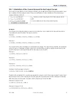
3.3.1
ATEX & IECEx Marking
II 3 G Ex nA IIC T4 Gc, DEMKO 16 ATEX 1591X
Ex nA IIC T4 Gc, IECEx ULD 16.0022X
Ta: -20 °C to +60 °C
For Relay Modules:
II 3 G Ex nA nC IIC T4 Gc, DEMKO 16 ATEX 1591X
Ex nA nC IIC T4 Gc, IECEx ULD 16.0022X
Ta: -20 °C to +60 °C
3.4
Spring-style System Cabling
RSTi-EP modules (except HD modules) and network adapters are equipped with the
spring-style
connector system. Single-strand and fine-strand lines with wire-end ferrules can be inserted without
the need for a tool. Lines with a cross-section measuring between 0.14 mm
2
and 1.5 mm
2
(AWG 26
–
16) can be connected.
The external dimensions of the crimped wire-end ferrules must conform to IEC
‑
60947-1.
3.5
Current Demand and Power Supply
The RSTi-EP system uses three internal current paths:
The
I
SYS
system current path
supplies the communication part of the I/O modules; it is fed from the
network adapter input supply and cannot be interrupted by any module. The maximum current-
carrying capacity of I
SYS
allows a RSTi-EP station to be expanded with a maximum of 64 active
modules without having to refresh the power.
The
I
IN
input current path
supplies the input circuit of the input modules as well as the connected I
S
sensors. The current must be refreshed with EO-7631 (power feed in) modules as required. These EP-
7631 modules isolate the input current path towards the left (towards the network adapter), and as a
result start a new electricity segment towards the right.
The
I
OUT
output current path
supplies the output circuit of the output modules with power, as well as
the connected I
L
actuators. The current must be refreshed with the EP-7641 (power feed-out), as
required. These EP-7641 modules isolate the output current path to the left (towards the network
adapter), and as a result start a new electricity segment to the right.
Note:
The design of the power supply being used must take start-up peaks into account.
3.5.1
Power Supply Derating
The power supply is restricted according to the temperature. The following values apply for the
horizontal and vertical positioning of the RSTi-EP station:
Temperature-dependent Values for the Power Supply
Horizontal
Vertical
Network Adapter power supply
60 °C / 140 °F : 2 x 8 A
55 °C / 131 °F : 2 x 10 A
55 °C / 131 °F : 2 x 6 A
50 °C / 122 °F : 2 x 8 A
Power-feed module power supply
60 °C / 140 °F : 1 x 10 A
55 °C / 131 °F : 1 x 8 A
Summary of Contents for RSTi-EP
Page 1: ...RSTi EP User Manual GFK 2958E November 2017...
Page 23: ...Chapter 1 Introduction GFK 2958E RSTi EP User Manual 19 Notes...
Page 56: ...Chapter 3 Configuration GFK 2958E RSTi EP User Manual 52 Notes...
Page 183: ...Chapter 5 Detailed Descriptions of I O Modules GFK 2958E RSTi EP User Manual 179 EP 5111...
Page 184: ...Chapter 5 Detailed Descriptions of I O Modules GFK 2958E RSTi EP User Manual 180 EP 5111...
Page 316: ...Chapter 5 Detailed Descriptions of I O Modules GFK 2958E RSTi EP User Manual 312 Notes...
Page 330: ...Chapter 6 Installation GFK 2958E RSTi EP User Manual 326 Notes...
Page 344: ...Chapter 7 Earthing and Shielding GFK 2958E RSTi EP User Manual 340...
Page 345: ...Chapter 7 Earthing and Shielding GFK 2958E RSTi EP User Manual 341 Notes...
Page 385: ...Chapter 8 Web Server GFK 2958E RSTi EP User Manual 381 Notes...
Page 401: ...Chapter 11 Disassembly and Disposal GFK 2958E RSTi EP User Manual 397 Notes...
Page 413: ...Chapter 12 LED Indicators and Troubleshooting GFK 2958E RSTi EP User Manual 409 Notes...
Page 416: ...Chapter 14Accessories and Replacement Parts GFK 2958E RSTi EP User Manual 412 Notes...


