background image

18

49-5000517  Rev. 2

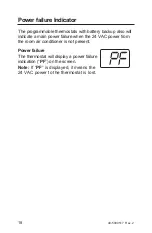
Power failure Indicator

The programmable thermostats with battery backup also will 
indicate a main power failure when the 24 VAC power from 
the room air conditioner is not present.

Power failure

The thermostat will display a power failure 
indication (“

PF

”) on the screen.

Note: 

If “

PF

” is displayed, it means the 

24 VAC power to the thermostat is lost.

Summary of Contents for RAK149P2

Page 1: ...CONFIGURATION MODE 8 OPERATING FUNCTIONS 10 TESTING THE THERMOSTAT 11 PROGRAMMING 13 LOW BATTERY 17 POWER FAILURE INDICATOR 18 TROUBLESHOOTING TIPS 20 LIMITED WARRANTY 24 RAK149P2 Owner s Manual Installation Instructions 49 5000517 Rev 2 10 20 GEA GE is a trademark of the General Electric Company Manufactured under trademark license ...

Page 2: ...se this thermostat only as described in this manual Electrical rating 24 VAC 18 30 VAC 1 amp maximum per terminal 4 amp maximum total load Operating temperature range 40 F 99 F 4 C 37 C Temperature set range 60 F 85 F 15 C 29 C Accuracy 1 F 0 5 C System configurations Factory Setting 2 stage heat heat pump resistance heat 1 stage cool 1 speed fan Alternate Setting 1 stage heat resistance heat 1 st...

Page 3: ...INTRODUCTION OVERVIEW Display THERMOSTAT CONTROL Auto Cool Off Heat On MODE HOLD Display Function Switch Fan Auto On Switch Mode Hold Switch Up Down Buttons Up Down Buttons Mode Hold Switch Wiring Channel Mounting Hole Function Switch Fan Auto On Switch Batteries Mounting Hole Reset Button ...

Page 4: ...ld expose the wires 3 Label the existing wires with the enclosed wire labels before removing wires 4 After labeling wires remove wires from wire terminals 5 Remove existing thermostat base from wall 6 Refer to the following section for instructions on how to install this thermostat PACKAGE CONTENTS TOOLS REQUIRED Package includes Thermostat on base thermostat cover 2 AAA batteries wiring labels sc...

Page 5: ...m working area 7 Using a 3 16s drill bit drill holes in the locations you have marked for mounting 8 Use a hammer to tap supplied anchors in mounting holes 9 Align thermostat base with mounting holes and feed the control wires through the wire opening 10 Seal hole for wires behind thermostat with non flammable insulation or putty or use a wall plate obtainable from a local hardware or home buildin...

Page 6: ...e 16 Plug the unit in or turn on power to the system at the main service panel 17 Test thermostat operation as described in the Testing the Thermostat section INSTALLATION INSTRUCTIONS Wiring diagrams Table 1 Terminals for five wires 1 stage heat 1 stage cool system Note Connect G terminal of thermostat to Zoneline GL terminal for low fan speed or terminal GH for high fan speed Only one can be sel...

Page 7: ...rminals for six wires 2 stage heat 1 stage cool system INSTALLATION INSTRUCTIONS B G Y W C R Note Connect G terminal of thermostat to Zoneline GL terminal for low fan speed or terminal GH for high fan speed Only one can be selected ...

Page 8: ... the previous screen 5 To save the changes and exit configuration mode slide the Function switch to Heat or Cool Configuration Mode Settings The setup screens for Configuration Mode are as follows 1 Temperature Scale F or C Choose Fahrenheit or Celsius Press the or button to select Press the Hold button to advance to the next screen NOTE Default factory setting is Fahrenheit 2 Heat System Check mo...

Page 9: ...m Cool Setpoint 60 64 66 68 70 72 74 76 F 15 17 19 20 21 22 23 24 C Adjust to control the minimum Cool set temperature allowed Press the or button to select Press the Hold button to advance to the next screen Note Default factory setting is 60 F 15 C 6 Maximum Heat Setpoint 65 70 72 74 76 78 80 85 F 18 21 22 23 24 26 27 29 C Adjust to control the maximum Heat set temperature allowed Press the or b...

Page 10: ...t In this mode the thermostat controls the heating system Press the Mode button to enter exit the Program Heat mode In Program Heat mode PROG displays the thermostat will follow the program schedule that is stored in memory Hold When in Programmable Cool or Programmable Heat you can lock in the present settings indefinitely by pressing the Hold button once PROG flashes Press Hold button again to l...

Page 11: ...On position 2 Indoor fan turns on 3 Slide Fan Auto On switch to Auto position 4 Indoor fan turns off Cool Test 1 Slide Function switch to Cool position Cool mode screen is displayed 2 Adjust set temperature so it is 5 degrees below room temperature 3 Air conditioning should come on within a few seconds 4 Adjust the set temperature so it is 2 degrees above the room temperature and the A C should tu...

Page 12: ...egrees above room temperature 3 Heat should come on within a few seconds 4 Adjust the set temperature so it is 2 degrees below the room temperature and the heat should turn off Note There is a 3 minute time delay and a 3 minute minimum run time for the compressor when it turns on off On some models the fan may also have a minimum run time off time delay PM HEAT ...

Page 13: ...splay shows the day currently set on the thermostat 01 Monday 02 Tuesday etc 5 Press the or button to set the current day of the week 6 Press the Hold button to go to the programming schedule or slide the Function switch to Cool or Heat positions to lock the values into memory The programmable thermostat comes preprogrammed with the following schedule Factory Programming Settings Setting the time ...

Page 14: ...and PROG is displayed 4 Press the or button to change the day you want to program 01 05 Monday Friday individually 67 program Saturday and Sunday at the same time 17 program every day of the week at the same time 15 program Monday Friday at the same time 5 Press the Hold button to advance to the next parameter Period is displayed MORN DAY EVE NITE Note You can always press the Mode button to retur...

Page 15: ... adjust heat set temperature 11 Press the Hold button to advance to the next screen Cool temperature is displayed 60 F to 85 F 15 C to 29 C 12 Press the or button to adjust cool set temperature 13 Press the Hold button to advance to the next screen Repeat steps 1 13 to program each day of the week individually Note When programming is complete slide the Function switch to Heat or Cool to exit Prog...

Page 16: ...E NITE HEAT HEAT HEAT HEAT COOL COOL COOL COOL FRIDAY 05 MORN DAY EVE NITE HEAT HEAT HEAT HEAT COOL COOL COOL COOL THURSDAY 04 MORN DAY EVE NITE HEAT HEAT HEAT HEAT COOL COOL COOL COOL WEDNESDAY 03 MORN DAY EVE NITE HEAT HEAT HEAT HEAT COOL COOL COOL COOL MONDAY 01 MORN DAY EVE NITE HEAT HEAT HEAT HEAT COOL COOL COOL COOL TUESDAY 02 MORN DAY EVE NITE HEAT HEAT HEAT HEAT COOL COOL COOL COOL ...

Page 17: ...ndicator The programmable thermostats with battery backup have a low battery warning screen Low battery warning The thermostat will display a low battery indication The low battery warning will be flashing until batteries are replaced ...

Page 18: ...ttery backup also will indicate a main power failure when the 24 VAC power from the room air conditioner is not present Power failure The thermostat will display a power failure indication PF on the screen Note If PF is displayed it means the 24 VAC power to the thermostat is lost ...

Page 19: ...49 5000517 Rev 2 19 Notes ...

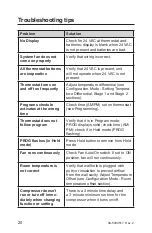
Page 20: ...rong time Check time AM PM set on thermostat see Programming Thermostat does not follow program Verify that it is in Program mode PROG displays solid check time AM PM check if in Hold mode PROG ÀDVKLQJ 352 ÀDVKHV LQ ROG mode Press Hold button to remove from Hold mode Fan runs continuously Check Fan Auto On switch If set to ON position fan will run continuously Room temperature is not correct Verif...

Page 21: ...e IDQ PD KDYH D PLQLPXP UXQ WLPH Rႇ time delay displays on screen Replace batteries with 2 fresh AAA alkaline batteries PF displays on screen Check for 24 VAC at thermostat Display reads 12 00 PM Set clock time Problem not listed above Press the Reset button once Reset button function time day and mode will be changed to the factory settings Display is refreshed ...

Page 22: ...22 49 5000517 Rev 2 Notes ...

Page 23: ...49 5000517 Rev 2 23 Notes ...

Page 24: ...ply voltage accident fire floods or acts of God Ŷ QFLGHQWDO RU FRQVHTXHQWLDO GDPDJH FDXVHG E SRVVLEOH GHIHFWV ZLWK this thermostat Staple your receipt here Proof of the original purchase date is needed to validate the warranty This limited warranty is extended to the original purchaser and any succeeding owner for products purchased for use within the USA and Canada In Alaska the limited warranty ...

Reviews: