– 58 –
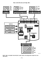
Main Control Board (Low-Voltage Side)
1
5
1
10
1
9
J1
J5
6
J3
J2
1
1 COMM
2 +12V
3 -COM
4 DI
5 DO
J4
1
8
DEFROST HEATER ON TIME
(MINUTES)
COMPRESSOR RUN TIME
(MINUTES)
ACCUMULATED FF AND FRZ
DOOR OPENINGS (MINUTES)
THERMISTOR
INPUTS
ENCODER
INPUTS
MODEL
SELECT
COMMUNICATION
INPUT/OUTPUT
DAMPER
COILS
FAN OUTPUTS
INPUTS
PROCESSING
UNIT
1 - Blk
2 - Red
3 - Blu
4 - Pur
5 - Wht
1 - Yel
2 - Red / Blk
3 - Wht / Brn
4 - Blu / Yel
1 - Blu / Red
2 - Yel
3 - Red / Wht
4 - Blu / Wht
5 - Blu
J4
J2
J3
J1
8 - Red
7 - Not Used
6 - Blk / Wht
5 - Yel
4 - Yel / Blk
3 - Wht
2 - Blu / Wht
1 - Blu
GEA00906
NOTE: Refer to the Main Control Board Locator Tables in the Diagnostics chapter for more
information.
Summary of Contents for PSC21MGM
Page 1: ......
Page 32: ...30 Notes...
Page 33: ...31 Notes...
Page 63: ...61 Schematics...
Page 64: ...62...
Page 66: ...64...
Page 67: ...65...
Page 68: ...66...
Page 69: ...67...
Page 70: ...68 Ref No Part Number Description 228 WR85X10022 Low Side Assembly...
Page 71: ...69...
Page 72: ...70...
Page 73: ...71...
Page 74: ...72...
Page 75: ...73...
Page 76: ...74...


