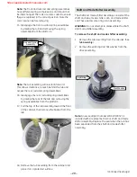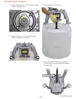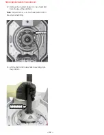
– 25 –
Inverter/Motor
The inverter/motor assembly receives 120 VAC,
which the inverter converts to approximately 340
VDC. The inverter then uses pulse width modulation
(PWM) to supply the motor with an AC varying
frequency to control speed.
Note:
There is no location to check inverter output
voltage to the motor. Voltage given is for information
only.
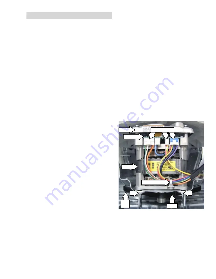
The inverter/motor assembly consists of a motor
and inverter board. A brake resistor is molded into
the underside of the inverter cover and absorbs
energy from the reversing of the motor during the
braking cycle. A Hall effect sensor mounted on the
inverter board measures motor speed (RPM).
The motor and inverter are available only as an
assembly.
WARNING:
Do not attempt to remove the inverter
cover to service the board or brake resistor.
Note:
There is a non re-settable fuse, located in
the motor harness along the right side of the
cabinet. If the fuse is open, agitate, spin, and
mode shifting will not occur.
If the motor speed sensor fails, the motor will
not run.
Since the electronic control receives no
feedback from the inverter motor assembly, if
the motor is not operating, the washer will still
fill with water, count down on the display, and
drain.
If during an agitation cycle, water leaks from
the tub and resets the pressure switch, the
main control stops the motor, the inverter goes
through the mode shifter spin program to de-
energize the cam and the washer starts to refill
with water. The motor will not run again until the
pressure switch is satisfied, at which time the
inverter control will run the mode shifter agitate
program.
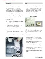
If the mode shifter circuit fails or the coil opens,
the tub will move back and forth with the
agitator during the wash cycle.
•
•
•
•
•
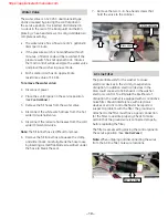
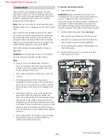
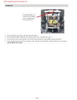
Disconnect
Wire Retainer
Belt
Drive
Pully
Inverter
Motor
Cover
To remove the inverter/motor:
Disconnect power.
WARNING:
Exposed terminals, PC board, and
rotating parts may cause injury and/or electrical
shock. To reduce the risk of electrical shock,
disconnect power and allow at least 5 minutes for
capacitors to discharge before servicing motor.
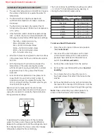
An audible clicking sound will be heard when the
inverter capacitor discharges (inrush relay closing).
Remove the front panel. (See
Front Panel
.)
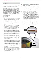
Disconnect 3 wire harnesses from the motor.
Release the compression tabs that attach the
wire retainer to the front of the platform.
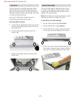
Remove the belt by rolling it off the bottom of
the motor pulley.
Remove the front two
3
/
8
-in. motor nuts and
loosen the rear 2 nuts.
1.
2.
3.
4.
5.
6.
(
Continued next page
)

