– 22 –
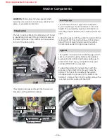
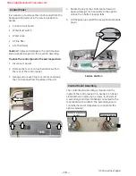
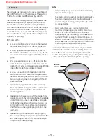
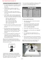
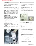
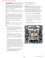
To remove the ATC thermistor:
Place the control panel in the service position.
(See
Control Panel
.)
Disconnect the wire harnesses on the main
control board. Remove the 2 wires and the
pressure hose attached to the water level
switch. (See
Water Level Switch
.)
Remove the control panel from the washer.
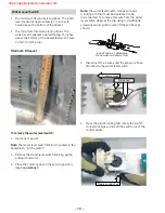
Remove the cover/lid assembly. (See
Cover/Lid
Assembly
.)
From inside the tub, remove the two ¼-in.
hex-head screws that attach the funnel to the
washer.
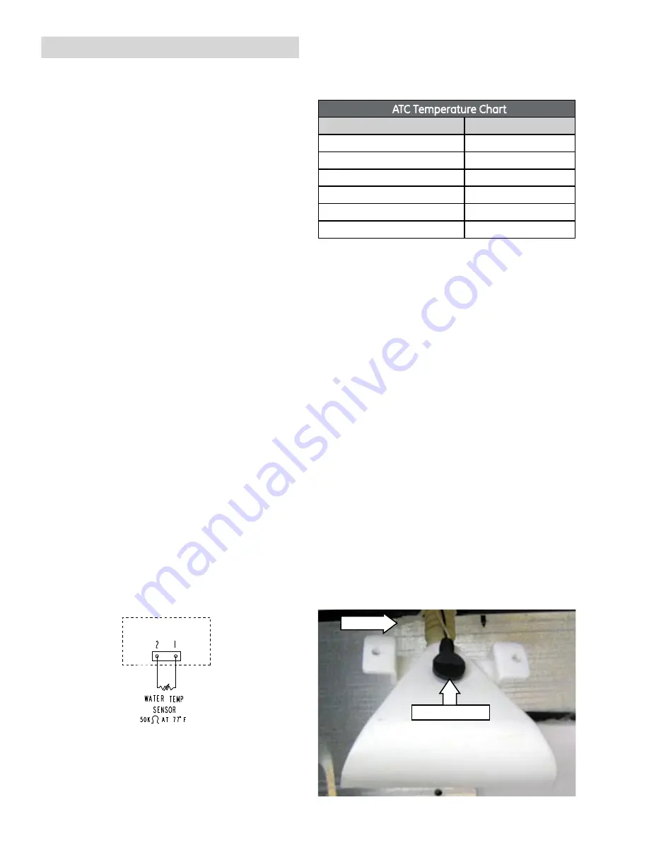
Remove the plastic wire tie, pull and unsnap the
thermistor from the top of the fill funnel. Pull the
wires and connector down through the opening.
Note:
Make certain the gray rubber gasket is in
place on the thermistor when reassembling.
1.
2.
3.
4.
5.
6.
ATC Thermistor
Wire Tie
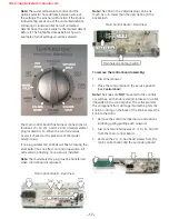
The main control should fill the tub with water within
+/- 10 to 15°F of set temperature by opening or
closing the hot and cold water valves.
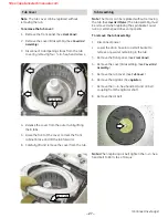
ATC Temperature Chart
Temperature Setting
Water Temperature
Tap Cold
Cold Tap Water
Cold
62°F ( +/- 10°F )
Cool
70°F ( +/- 10°F )
Colors
80°F ( +/- 10°F )
Warm
95°F ( +/- 10°F )
Hot
125°F ( +/- 15°F )
Automatic Temperature Control (ATC)
The automatic temperature control (ATC) is a feature
that utilizes a thermistor to regulate the water fill
temperature.
The thermistor has a negative temperature
coefficient (as temperature increases, resistance
decreases).
The thermistor is located in the outlet of the fill
funnel and will measure 50K
Ω
at room temperature
(77°F / 25°C).
If the thermistor reads outside the expected range
(10K - 120K
Ω
), the main control will default to the
following pre-programmed fill temperature settings:
Tap Cold = cold water valve only
Cold = cold water valve only
Cool = hot and cold water valves
Colors = hot and cold water valves
Warm = hot and cold water valves
Hot = hot water valve only
When both valves are energized, the internal orifices
in the valves meter the flow to a 60% cold and 40%
hot ratio.
With the lid open, ATC will remain activated. The
temperature of the water entering the washer
with the lid open may vary greatly from customer
expectations due to the cycling of the fill valve
solenoids.
Extreme water temperatures at low pressure can
cause the ATC to use it’s maximum number of
activations and revert to a preset fill routine. The
main control will not allow the water valve to cycle
more than 25 times per fill.
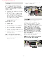
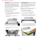
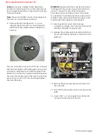
Resistance can be measured at the wire harness
located on the control board location J5. Make sure to
unplug the connector to isolate the thermistor before
taking resistance readings.
•
•
•
•
•
•
•
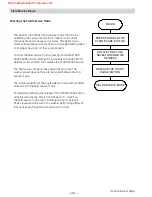
To determine the temperature of the incoming
water, the main control measures the difference
between the voltage sent and the voltage returned
from the thermistor. The main control then makes
temperature adjustments accordingly.
MAIN CONTROL BOARD
J5

