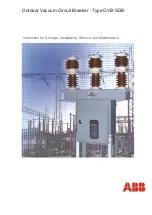

Power Break®
II
Circuit Breakers
Draw-Out Breaker Installation
:·
.1.
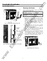
Racking Tool
Figure
7
Wrench attached to the breaker racking shaft.
Substructure
Rejection
Feature
.06in
minimum
Breaker
Rejection
Feature
Compartment
Position Indicator
Figure
8.
Compartment position indicator on the front of the breaker.
4
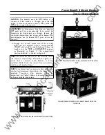
Removing the Breaker
Use the following procedure to remove the draw-out
breaker from the substructure.
CAUTION:
The breaker must be
OFF
before it is dis
connected and removed.
ATTENTION:
Le disjoncteur doit etre en position
OFF
avant qu'il ne soit debroche et depose.
1.
Engage the
1
!2
-inch square end of the racking
shaft with the supplied wrench, catalog number
TDORT, as illustrated in Figure
7,
and rotate the
shaft counter-clockwise to withdraw the breaker to
the
TEST
or
DISCONNECTED
position. The
compartment position indicator is shown i n
Figure 8.
2.
Pull the substructure rails out as far as possible
until they drop into the horizontal locked posi
tion, as illustrated in Figure
9.
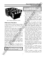
3.
From the
DISCONNECTED
position, pull the
breaker out on the rails until the front rollers fall
into the detent, as illustrated in Figure
6.
4.
The breaker can now be rotated about the front
roller by pulling forward, as illustrated in Figure
10, for inspection of the rear of the breaker, or it
can be completely removed after attaching the
Lifting Bar, as illustrated in Figures
4
and
5.
Figure
9.
Withdrawing the substructure rails.
www
. ElectricalPartManuals
. com