GEK-106426B
MIB High Impedance Bus Differntial Relay
3-9
3 HARDWARE
3.4 HIGH-SPEED OVERCURRENT PROTECTION MODULE
3
3.4HIGH-SPEED OVERCURRENT PROTECTION MODULE
3.4.1 MECHANICAL DESCRIPTION
The high-speed overcurrent module is available in a box of a quarter of 19” rack four units high. The metallic case of the
unit is highly resistant to corrosion. It is made of stainless steel (AISI 304), coated with an epoxy layer, and the rest of the
metallic pieces are covered with a high quality resistive coating that has successfully passed at least 96 hours in the salt
spray chamber (S/N ASTM B-117).
The front of the relay is made of a shielded high quality thermoplastic, flame retardant (V0), highly resistive material,
which guarantees the unit’s immunity to all types of EMI/RFI/ESD interference. As well, an IP52 (IEC 529) protection
degree against dust and water through the front and with the relay mounted in the panel.
The modular design of the relay simplifies repair or replacement of its components, without the need to manipulate the
wiring. These types of operations must be performed exclusively by qualified personnel and only after removing auxiliary
voltage from the unit.
3.4.2 MOUNTING
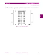
The high-speed overcurrent module is secured to the panel with the 4 M6 screws provided with the unit. This allows the
user access to the front keypad, display and communication port. The wiring is at the rear of the unit. The drilling
dimensions are shown on the drilling dimension diagram.
Figure 3–8: HIGH-SPEED OVERCURRENT PROTECTION MODULE MOUNTING DIAGRAM
3.4.3 REAR DESCRIPTION
The module is wired through the terminal blocks located at the rear of the unit. In these terminal blocks, current terminals
are shorted two-by-two when the module is extracted, so that the CT secondary never remains open. The maximum
recommended cable section for this terminal board, with the appropriate terminal, is 6 mm2 (AWG 10).


