05-4055A01, Rev. E
MDS entraNET Technical Manual
159
NOTE:
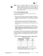
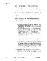
Some EU countries mandate lower power outputs and
frequency limitations from those referenced here. For
example, in France, the transceiver may only be operated in
band C (2.4528-2.4782 GHz) at a power level of 10 dBm. Be
sure to check the requirements for your region before placing
the transmitter on the air.
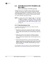
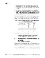
6.4.1 Calculating System Gain
To determine the maximum allowable power setting of the radio,
perform the following steps:
1. Determine the antenna system gain by subtracting the feedline loss
(in dB) from the antenna gain (in dBi). For example, if the antenna
gain is 10 dBi, and the feedline loss is 2 dB, the antenna system gain
is 8 dB.
2. Subtract the antenna system gain from 20 dBm (the maximum
allowable EIRP). The result indicates the maximum transmitter
power (in dBm) allowed under the rules. In the example above, this
is 12 dBm.
3. If the maximum transmitter power allowed is less than 20 dBm,
reduce the transmit power accordingly using the radio menu system
(
Main Menu>Radio Configuration>RF Output Power Setpoint
), or introduce
additional feedline loss. The EIRP of the antenna system should
never exceed 20 dBi.
For convenience,
Table 6-6
lists several antenna system gains and shows
the maximum allowable power setting of the radio. Note that a gain of
0 dB or less entitles you to operate the radio at the full power output of
+20 dBm (100 mW). To convert dBm to Watts, refer to
Table 8-4 on
Page 193
.
* Most antenna manufacturers rate antenna gain in dBd in their litera-
ture. To convert to dBi, add 2.15 dB.
† Feedline loss varies by cable type and length. To determine the loss
for common lengths of feedline, see
Table 6-2 on Page 155
.
Table 6-6. Antenna System Gain versus Power Output Setting
(for ETSI compliance)
Antenna System Gain
(Antenna Gain in dBi*
minus Feedline Loss in dB†)
Maximum Power
Setting
(in dBm)
EIRP
(in dBi)
0 (or less)
20
20
3
17
20
6
14
20
9
11
20
10
10
20
Summary of Contents for MDS entraNET 900
Page 10: ...LA N CO M1 CO M2 PW R LIN K viii MDS entraNET Technical Manual 05 4055A01 Rev E...
Page 12: ...2 MDS entraNET Technical Manual 05 4055A01 Rev E LA N CO M1 CO M2 PW R LIN K...
Page 24: ...14 MDS entraNET Technical Manual 05 4055A01 Rev E LA N CO M1 CO M2 PW R LIN K...
Page 26: ...16 MDS entraNET Technical Manual 05 4055A01 Rev E LA N CO M1 CO M2 PW R LIN K...
Page 38: ...28 MDS entraNET Technical Manual 05 4055A01 Rev E LA N CO M1 CO M2 PW R LIN K...
Page 110: ...100 MDS entraNET Technical Manual 05 4055A01 Rev E LA N CO M1 CO M2 PW R LIN K...
Page 130: ...120 MDS entraNET Technical Manual 05 4055A01 Rev E LA N CO M1 CO M2 PW R LIN K...
Page 156: ...146 MDS entraNET Technical Manual 05 4055A01 Rev E LA N CO M1 CO M2 PW R LIN K...
Page 158: ...148 MDS entraNET Technical Manual 05 4055A01 Rev E LA N CO M1 CO M2 PW R LIN K...
Page 176: ...166 MDS entraNET Technical Manual 05 4055A01 Rev E LA N CO M1 CO M2 PW R LIN K...
Page 186: ...176 MDS entraNET Technical Manual 05 4055A01 Rev E LA N CO M1 CO M2 PW R LIN K...
Page 188: ...178 MDS entraNET Technical Manual 05 4055A01 Rev E LA N CO M1 CO M2 PW R LIN K...
Page 204: ...194 MDS entraNET Technical Manual 05 4055A01 Rev E LA N CO M1 CO M2 PW R LIN K...
Page 218: ...I 8 MDS entraNET Technical Manual 05 4055A01 Rev E...


