© 2017 General Electric Company. All rights reserved
.
26 |
=
GE Oil & Gas
GE Oil & Gas
ES-776 Rev L
Page 10 of 14
Copyright 2016. This document and all information herein is the property of Dresser Inc.
7
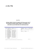
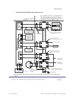
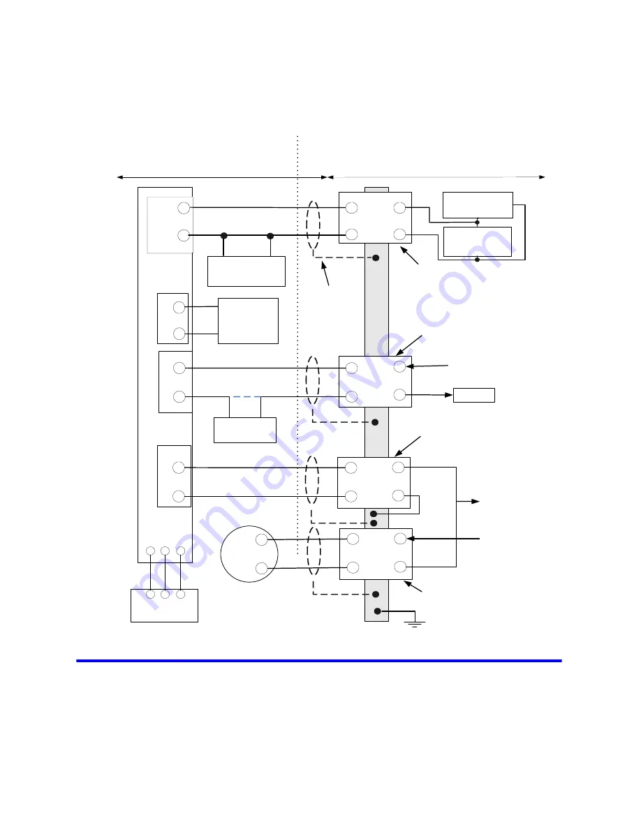
Intrinsically Safe Installation Wiring Requirements
Optional
Intrinsically Safe
Process Variable
Trnsmitter
NON- HAZARDOUS LOCATION-
UNSPECIFIED EXCEPT
THAT BARRIERS MUST NOT BE SUPPLIED FROM NOR
CONTAIN UNDER NORMAL OR ABNORMAL CONDITIONS A
SOURCE OF POTENTIAL WITH RESPECT TO EARTH IN
EXCESS OF 250 VOLTS RMS OR250 VOLTS DC
HAZARDOUS LOCATION
SEE8.1 , 8.2
1
2
4
3
SV
IF
F
P
os
iti
on
er
SW
1
(D
O
)
-
+
Equi- Potential
Optional Field
Load
Shunt Zener Diode Safety Barrier
Controller Output Type (See 8.3)
24 VDC from DCS
To DCS DI
Shunt Zener Diode Safety
Barrier Switch Type Barrier (See 8.5)
Cable Shield
SVI FF Remote
Mount
- - -
- - -
Remote
1
2
1 to 5 Volts to
control system
4
3
AI
_
P
V
1
-5
V
D
C
-
+
Shunt Zener Diode Safety
Barrier Switch Type Barrier
( See8.4)
1
2
4
3
Shunt Zener Diode Safety Barrier
-
Controller Output Type (See 8.4)
-
+
Transmitter
24 VDC from
Control System
See Note8.6
DI
+
-
Simple Passive
Apparatus
(Switch, relay)
+
-
F
o
unda
ti
on
Fi
e
b
u
s
dl
4
3
1
2
( See
8. )
Optional Hand Held
8
Communicator
Foundation Field bus
Set Point from
Control system
Optional Hand Held
Communicator
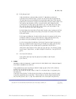
Each intrinsically safe cable must include a grounded shield or be run in a separate metal
conduit.
Summary of Contents for Masoneilan SVI FF
Page 4: ...This page intentionally left blank ...
Page 31: ......

