D
IRECTION
5750007-1EN, R
EV
. 1
LOGIQ E10 B
ASIC
S
ERVICE
M
ANUAL
Chapter 8 Replacement Procedures
8 - 309
Backplane installation
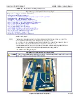
CAUTION
To avoid injury, handle the Backplane by the edges. There are two guides to guide the ECB onto the
Backplane, which protrude and are VERY SHARP.
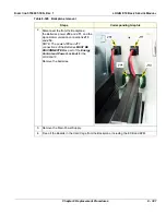
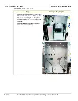
Table 8-330 Backplane installation
Steps
Corresponding Graphic
1.
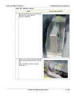
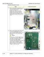
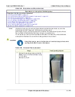
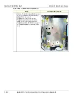
Grasping the outer edges of the Backplane, carefully place the Backplane toward the Card Cage,
guiding the connectors to the Main Power Supply into the Card Cage.
Install the 21 Phillips screws to secure and ground the Backplane to the Card Cage. Tighten
screws alternately.
2.
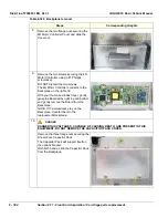
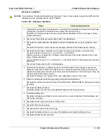
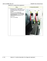
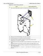
Re-connect the Subwoofer audio cable to
J9
on the Backplane.
3.
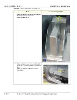
Re-install the Option Bracket. BE SURE to support the Bracket as it is being installed, it has
mass.
Re-install the five M6 screws that secure the Option Bracket to the Base Casting, loosely.
4.
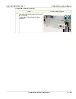
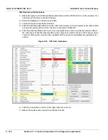
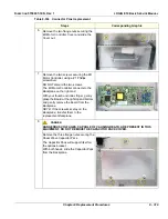
Re-install the four hex screwlocks (on the right) and two locking posts (on the left) to the
Connector Panel Torque to 0.6 +/- 0.1 Nm (0.4 +/- 0.07 lbf-ft).
Starting at the top, re-install the 7 Phillips screws that secure the Option Bracket to the Card
Cage. Tighten alternately.
Torque the M6 screws to 3.7 +/- 0.6 Nm (2.7 +/- 0.44 lbf-ft), ONLY the M6 screws are torqued to
this value.
Re-connect Subwoofer to
J9
, on the Backplane.
5.
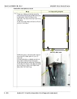
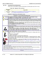
Position the Option Box up slightly and turn it toward the Main Power Supply to access the
Network Cable at the bottom of the Rear I/O. Re-connect the Network Cable and continue to
position the Option Box onto the studs that secure the Option Box to the Card Cage. Three are
underneath the Option Box, in slots.
Re-install the flange nuts. Tighten all the nuts, alternately, using a 7 mm driver.
6.
Place the Subwoofer cable and grounding clamp into the Option Box.
Re-install the screw to secure the clamp to the Option Box. MAKE SURE the clamp is grounding
the cable.
7.
Re-install the Battery Bracket.
Install the flange nuts and secure the Battery Bracket to the Option Bracket.
8.
Install the Battery last.
Re-install all Options and Option covers removed re-connect all cabling to the Backplane and
CW Cable, if present.
9.
Re-install Printer Tray and Printer or Printer Filler.
10. Re-install Main Power Supply.
11. Re-seat all the boards in the Card Cage.
12. Re-install the Battery Bracket, re-connect the Batteries and install the Battery Cover.
13. Re-install all other covers removed.
Summary of Contents for LOGIQ E10
Page 1: ...LOGIQ E10 Basic Service Manual 5750007 1EN Rev 1 Version R1 2018 GENERAL ELECTRIC COMPANY...
Page 2: ......
Page 4: ...DIRECTION 5750007 1EN REVISION REV 1 LOGIQ E10 BASIC SERVICE MANUAL ii...
Page 5: ...DIRECTION 5750007 1EN REV 1 LOGIQ E10 BASIC SERVICE MANUAL iii...
Page 6: ...DIRECTION 5750007 1EN REVISION REV 1 LOGIQ E10 BASIC SERVICE MANUAL iv...
Page 7: ...DIRECTION 5750007 1EN REV 1 LOGIQ E10 BASIC SERVICE MANUAL v...
Page 8: ...DIRECTION 5750007 1EN REVISION REV 1 LOGIQ E10 BASIC SERVICE MANUAL vi...
Page 9: ...DIRECTION 5750007 1EN REV 1 LOGIQ E10 BASIC SERVICE MANUAL vii...
Page 10: ...DIRECTION 5750007 1EN REVISION REV 1 LOGIQ E10 BASIC SERVICE MANUAL viii...
Page 11: ...DIRECTION 5750007 1EN REV 1 LOGIQ E10 BASIC SERVICE MANUAL ix...
Page 12: ...DIRECTION 5750007 1EN REVISION REV 1 LOGIQ E10 BASIC SERVICE MANUAL x...
Page 13: ...DIRECTION 5750007 1EN REV 1 LOGIQ E10 BASIC SERVICE MANUAL xi...
Page 14: ...DIRECTION 5750007 1EN REVISION REV 1 LOGIQ E10 BASIC SERVICE MANUAL xii...
Page 34: ...DIRECTION 5750007 1EN REV 1 LOGIQ E10 BASIC SERVICE MANUAL xxxii Hardware Kit 9 49...
Page 776: ...DIRECTION 5750007 1EN REV 1 LOGIQ E10 BASIC SERVICE MANUAL Index 4...
Page 777: ......

