background image

– 46 –

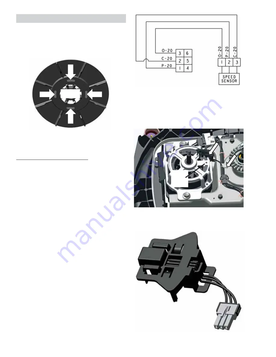
Pin 1 to pin 5 should read approximately 4.5 
VDC while rotating the basket by hand.

Speed/Hall Sensor Removal

Disconnect the speed/hall sensor from the drive 
motor and disconnect from the main harness.

There is a locating post on the bottom of the 
sensor that is pushed into an existing hole in the 
motor housing, when reinstalling.

The speed/hall sensor is mounted to the drive 
motor and sends a pulse signal back to the 
control board.  This is done when the magnet that 
is mounted in the drive motor pulley passes over 
the sensor.

If the control does not read any signal from the 
sensor from the movement of the motor, the 
washer cycle will stop.

6SHHG+DOO6HQVRU'LDJQRVLQJ

The speed/hall sensor can be diagnosed two 

GLႇHUHQWZD\V

‡

Enter the Service Mode and Run the Spin 
Test

If the speed/hall sensor is bad or 
disconnected, the basket will start to spin 

QRUPDOO\DW¿UVW$IWHUVHFRQGVPRWRU

power will be stopped and a locked rotor fault 
will be set.  If the washer continues to spin for 
at least 15 seconds, the speed/hall sensor is 
good.

‡ 7HVWWKH9ROWDJH

From connector pins 3 to 5 on the J602 
should read approximately 9 VDC.

Magnet

Guide 

post 
hole

  Speed/Hall Sensor

Summary of Contents for GUD24ESSMWW

Page 1: ...D24ESSMWW GUD24GSSMWW XUD27ESSMWW XUD27GSSMWW Technical Service Guide 24 and 27 in Unitized Laundry Centers EASY CARE COTTONS COTTONS DELICATES PERMANENT PRESSS DELICATES S WASHER DRYER TIMED DRY DRYER TEMPERATURES LOAD SIZE WASHER TART August 2018 ...

Page 2: ...ctrical power is required for diagnosis or test purposes disconnect the power immediately after performing the necessary checks RECONNECT ALL GROUNDING DEVICES If grounding wires screws straps clips nuts or washers used to complete a path to ground are removed for service they must be returned to their original position and properly fastened GE Appliances a Haier Company Copyright 2018 All rights ...

Page 3: ...r Operation Overview 15 LUÀRZ 16 Component Locator Views 17 Washer Components 17 Electric Dryer Components 18 Gas Dryer Components 19 Washer Main Board Connector Locator View 20 Components 21 Shipping Rod 21 Leveling The Washer 21 Service Panel 21 Control Panel 22 Washer Selector Switches 22 User Interface Board 23 Main Board 23 Dryer Timer and Start Switch 24 Timer Voltage Dropping Resistor 25 Dr...

Page 4: ...mostat 35 High Limit Thermostat 36 Burner Assembly and LP Conversion 36 Gas Valve Coils 36 Gas Valve 37 Flame Detector 39 Ignitor 39 Ignitor Circuit Operation 40 Washer Components 41 Single Action Agitator 41 Front Panel 41 Top Cover Assembly 42 Drain Pump 42 Tub Cover 43 Suspension Rods 43 Drive System 45 Washer Drive Belt 45 Drive Transmission Pulleys 45 Speed Hall Sensor 46 Washer Drive Motor 4...

Page 5: ...omatic Temperature Control ATC 57 Troubleshooting 60 Diagnostics and Service Information 62 Dryer Timer Chart 62 Washer Field Service Mode 63 Fault Code 67 Fault Code Binary Display 75 Wiring Diagrams 77 Electric Dryer 77 Electric Dryer Long Vent Blower Motor Circuit 78 Gas Dryer 79 Washer 80 Index 81 ...

Page 6: ...e stored energy Step 3 Isolate the appliance Step 6 Try It verify that the appliance is locked out GE Factory Service Employees are required to use safety glasses with side shields safety gloves and steel toe shoes for all repairs Steel Toed Work Boot Electrically Rated Glove and Dyneema Cut Resistant Glove Keeper Dyneema Cut Resistant Glove Cut Resistant Sleeve s Plano Type Safety Glasses Brazing...

Page 7: ...LDO QXPEHU LGHQWLI WKH PRQWK DQG HDU RI PDQXIDFWXUH 7KH OHWWHU designating the year repeats every 12 years Example LA123456S June 2013 A JAN D FEB F MAR G APR H MAY L JUN M JUL R AUG S SEP T OCT V NOV Z DEC 2024 Z 2023 V 2022 T 2021 S 2020 R 2019 M 2018 L 2017 H 2016 G 2015 F 2014 D 2013 A Model Number G U D 2 7 E S S M W W Brand G General Electric X Crosley RQ JXUDWLRQ U Unitized Model Year M 201...

Page 8: ...ostat Temperature F Temperature C Open Close Open Close Drum Outlet 130 5 120 6 55 3 49 3 Control Outlet 210 5 180 6 99 3 82 3 RQWURO QOHW RQJ 9HQW Only 205 5 175 6 96 3 79 3 Safety 235 5 205 6 113 3 96 3 6DIHW RQJ 9HQW 2QO 225 5 195 6 107 3 91 3 LJK LPLW 315 8 250 15 157 6 121 9 Terminal Wire Color C Pink U Brown Yellow Y Yellow X Yellow A Orange T Tan S Blue B Red F Not Used Electric Dryer ...

Page 9: ...Thermostat Temperature F Temperature C Open Close Open Close Drum Outlet 130 5 120 6 55 3 49 3 Control Inlet 210 5 180 6 99 3 82 3 Safety 27 Models 280 5 240 12 138 4 116 7 Safety 24 Models 300 5 260 12 184 4 127 7 LJK LPLW 315 8 250 15 157 6 121 9 Terminal Wire Color C Pink U Brown Yellow Y Yellow X Yellow A Orange T Tan S Blue B Red F Not Used Gas Dryer ...

Page 10: ...tion Turning the knob after the cycle has started will stop the washer and change the cycle to the new selection Deep Rinse The status lights show the stage the washer is in When the selector knob is set to a new F FOH WKH VWDWXV OLJKWV ZLOO ÀDVK PRPHQWDULO VKRZLQJ WKH VWDJHV WKH F FOHV ZLOO JR WKURXJK E A E B Washer Models GUD27 XUD27 GUV27 Washer Model GUD24 ...

Page 11: ...Tap Cold uses incoming tap water which can provide energy savings For all other temperature selections a mixture of hot and cold water is used to achieve the ideal temperature for each temperature setting Load Size on some models 2ႇHUV D VHOHFWLRQ IURP VPDOO WR VXSHU RU SUHFLVH OO ZKLFK DXWRPDWLFDOO SURYLGHV WKH FRUUHFW amount of water suited to the size and type of load placed in the machine Prec...

Page 12: ...HQ ZLWK WKH OLG RSHQ H FHSW ZKHQ Precise Fill on some models is selected as the load size The lid must be closed to continue OOLQJ ZKHQ 3UHFLVH LOO LV VHOHFWHG If the machine is paused more than 24 hours with the lid closed the cycle will be cancelled and drain the water If the machine is paused more than 15 minutes with the lid open the F FOH ZLOO EH FDQFHOOHG DQG WKH ZDWHU ZLOO GUDLQ 7R VWRS WKH...

Page 13: ...p 4XLFN OXႇ RU IUHVKHQLQJ RU ÀXႈQJ XS DOUHDG GU FORWKLQJ IDEULFV OLQHQV DQG SLOORZV Use with OXႇ 1R HDW Provides 10 minutes of no heat tumbling Automatic cycles determine fabric dryness and provide automatic sensed drying The timer does not rotate during the cycle until the thermostats sense that the clothes are dry then the WLPHU URWDWHV DXWRPDWLFDOO WR 2ႇ Select Less Dry if you want your clothes...

Page 14: ...nly rigid metal 4 inches in diameter ductwork inside the dryer cabinet Use only rigid metal or 8 DSSURYHG ÀH LEOH PHWDO LQFKHV LQ GLDPHWHU GXFWZRUN IRU H KDXVWLQJ WR WKH RXWVLGH Do not use plastic or other combustible ductwork Use the shortest length possible Do not crush or collapse Avoid resting the duct on sharp objects Venting must conform to local building codes RDGLQJ DQG 8VLQJ WKH U HU 9HQW...

Page 15: ...afe limits The typical dryer cycle progresses as follows 1 A cycle is selected and the Start key is pressed 2 The motor is activated 3 7KH KHDWHU FRLOV EXUQHU IRU JDV PRGHOV DUH DFWLYDWHG 7KH FRLOV EXUQHU F FOH RQ DQG Rႇ WR achieve the desired temperature throughout the heating portion of the cycle 4 If an Auto Dry cycle is selected the heater coils burner for gas models are activated The coils EX...

Page 16: ... 16 LUÀRZ ...

Page 17: ... 17 Component Locator Views Continued Next Page Pressure Chamber Motor and Transmission Behind Front Motor Protector Drain Pump Tub Cover Pressure Hose Washer Components ...

Page 18: ...mit Thermostat Inlet Control Thermostat Safety Thermostat Motor and Blower Assembly Outlet Control Thermostat Idler Pulley Door Switch Connector Dryer Timer Connector Board Power Supply Connector Mica Heater Electric Dryer Components ...

Page 19: ... Thermostat Safety Thermostat Inlet Control Thermostat Motor and Blower Assembly Outlet Control Thermostat Door Switch Connector Dryer Timer Connector Board Power Supply Connector Burner Assembly Gas Dryer Components ...

Page 20: ...VAC input J511 Washer Drive Motor J512 Mode Shifter and Drain Pump J513 Lid Switch and Lid Lock J514 Water Valve J602 Speed Sensor RJ45 and User Interface Board J615 Personality Jumper J701 Thermistor J514 J511 J513 Pressure Sensor J602 J101 J512 J615 J701 ...

Page 21: ...llips or square drive screwdrivers can be used to extract or install these screws The rod is inserted and removed through a hole located on the lower right side of the cabinet and now passes behind the transmission The shipping rod passes through the chassis rod brackets and the platform brackets To level the washer tilt the washer forward to lift WKH UHDU OHJV Rႇ WKH ÀRRU WKHQ JHQWO VHW LW EDFN d...

Page 22: ...er Selector Switches Replacement 1 Remove the service panel See Service Panel in this section of this service guide 2 Pull the control knob straight out from the control panel 3 Place the control panel in the service position 4 Place the control panel in the service position See Control Panel in this section of this service guide 5 Lift the locking lever and rotate the selector switch counter cloc...

Page 23: ...rd is located behind the service panel It supplies power to all of the washer components The pressure sensor is also mounted to the main board Main Board Removal 1 Remove the service panel see Service Panel Removal in this section of the service guide 2 Remove the pressure sensor hose from the main board This is done by grasping the hose where it connects to the board rotate WKH WXEH ZKLOH DW WKH ...

Page 24: ...PDOO ÀDW EODGH VFUHZGULYHU SXVK in on the lock tab while rotating the timer clockwise The dryer timer start switch and timer voltage dropping resistor electric models only are attached to the dryer control bracket NOTE The dryer timer motor has an approximate resistance value of 2 4k ohms Electric Dryer Control Bracket Gas Dryer Control Bracket Dryer Start Switch Dryer Timer Dryer Start Switch Dry...

Page 25: ...oltage dropping resistor on electric models controls the run time during automatic cycles This 4500 ohm resistor is in series with the timer motor When the drum outlet thermostat RSHQV DQG WXUQV Rႇ WKH KHDW WKH UHVLVWRU GURSV the 240 VAC heater circuit to 120 VAC to run the timer motor NOTE If an open timer motor is present or if the timer fails to advance a properly heating automatic cycle to the...

Page 26: ...he top of the top bearing assembly and pull down and inward to release the assembly from the front panel 5 Unplug the harness connectors located below the right bottom corner of the front panel Two harness connectors for electric models two for gas models 6 Remove the four Phillips screws from the front of the panel NOTE In the following step DO NOT remove the two Phillips head screws from the top...

Page 27: ...rs from the trap duct assembly Caution Upon reassembly ensure that the door switch wiring is retained and routed properly to avoid contact with the drum NOTE The trap duct felt can be replaced by extracting the seal from the channel located in the trap duct assembly Trap Duct Assembly Drum Seal Wire Retainers The door switch is fastened to the front panel by two locking tabs one on each side When ...

Page 28: ...g dryer operation WARNING Sharp edges may be exposed when servicing the dryer Use caution to avoid injury and wear Kevlar gloves and sleeves or equivalent protection The drive belt is a 4 rib belt and extends from under the motor pulley over the top of the idler pulley and around the perimeter of the dryer drum See belt diagram Belt Installed on Pulleys in the next column Belt tension is maintaine...

Page 29: ...guide it out of the cabinet The drum shaft is attached to the rear of the drum with three T 20 Torx head screws The EHDULQJ FDQ EH UHPRYHG E SXOOLQJ LW Rႇ WKH VKDIW 7KH GUXP VKDIW DQG EHDULQJ W LQWR WKH EHDULQJ retainer in the center of the heater assembly HOHFWULF PRGHOV RU GLႇXVHU DVVHPEO JDV models To access the drum shaft and bearing it is necessary to remove the drum See Drum in this section ...

Page 30: ... base plate 4 Remove the idler assembly from the dryer Slot Idler Arm Motor Bracket The drive motor is a single speed dual shaft 1 4 hp 1725 rpm motor with an automatic reset overload protector The overload protector is an internal component of the motor and cannot be replaced separately The motor contains a centrifugal switch that serves three purposes It disengages the motor start winding M6 eng...

Page 31: ...sing plyers Then using a 15 16 in 24 mm socket remove the blower wheel from the motor shaft by turning it counter clockwise 12 Once the blower wheel is removed remove the two Phillips head screws that attach the front motor strap to the motor bracket 13 Lift and remove the motor and motor support from the motor bracket Motor and Blower Assembly Removal 1 Remove the drum See Drum in this section of...

Page 32: ...ess terminals at the 9 30 o clock position when looking at the machine from the front 1 of 2 Rear Motor Strap Front Motor Strap Motor Bracket Motor Support 1 of 2 Blower Wheel The long vent and blower motor was designed to be used where straight run venting can reach lengths up to 200 feet Depending on how many elbows and type of vent hood used will determine the maximum length the vent run can be...

Page 33: ...ghtly 1 Remove the 2 Phillips head screws that hold the top of the motor bracket to the blower housing 2 Remove two 1 4 inch hex head screws securing the drive motor to the chassis base 3 Rotate the drive motor to the right so the shaft will not interfere with the blower motor 4 Remove two 1 4 inch hex head screws securing the blower motor to the chassis base 5 Slide the blower motor and blower wh...

Page 34: ...afety thermostat is located on the top left area of the heater housing to the left of the inlet control thermostat On gas models the safety thermostat is located on WKH ULJKW VLGH RI WKH GLႇXVHU EHORZ WKH KLJK OLPLW thermostat The thermostat monitors incoming air temperature If the thermostat reaches a temperature beyond its maximum temperature rating it will trip and disable power to the heating ...

Page 35: ...VHU The inlet control thermostat on gas models utilize two locking tabs instead of a Phillips head screw 4 Lift and slide the thermostat from the heater DVVHPEO RU GLႇXVHU Electric Model Shown Inlet Control Thermostat 27 in Electric Model 24 in Gas Model Inlet Control Thermostat Inlet Control Thermostat The outlet control thermostat is located on the upper rear area of the blower housing The outle...

Page 36: ... that attaches the high limit thermostat to the heater DVVHPEO RU GLႇXVHU 4 Slide the thermostat from the heater assembly RU GLႇXVHU High Limit Thermostat 27 in Electric Model 24 in Gas Model High Limit Thermostat Main Coil Booster Coil Safety Coil The burner assembly has a gas valve that utilizes three coils A double coil safety and booster coils combined and a single main coil are located on top...

Page 37: ...on reassembly ensure the tab at the bottom of the combustion chamber is inserted into the slot located on the dryer chassis Double and Main Coils Removal 1 Remove the drum See Drum in this section of this service guide 2 Disconnect the wire harness from both coils 3 Note the position of the locator pins inserted in the coil bracket 4 Remove the two Phillips head screws that attach the coil bracket...

Page 38: ...et is inserted under the two tabs located in WKH GU HU ÀRRU Gas Valve Bracket Disconnect Disconnect Tab Tab Disconnect Caution The ignitor is very fragile To prevent breaking the ignitor care must be taken when removing or installing the gas valve 10 Lift the front of the combustion chamber then maneuver the gas valve assembly from the dryer 11 Remove the coils from the gas valve See Gas Valve Coi...

Page 39: ...embly ensure the tab at the ERWWRP RI WKH ÀDPH GHWHFWRU LV LQVHUWHG LQWR WKH slot located on the combustion chamber The ignitor is located at the end of the burner assembly in the combustion chamber opening and has a maximum rating of 4 amps The ignitor has an approximate resistance value of 40 to 400 ȍ The ignitor is attached to the gas valve bracket with a Phillips head screw To access the ignit...

Page 40: ...as valve 2 Neutral circuit is from the dryer harness through the door switch and motor switch M2 to M1 to the gas valve When the glo bar is heating the booster and safety coils are both energized and will open the safety YDOYH 7KH PDLQ YDOYH LV FORVHG DV LWV FRLO LV E SDVVHG E WKH 1 ÀDPH GHWHFWRU KHQ WKH JOR EDU UHDFKHV LJQLWLRQ WHPSHUDWXUH LQ DSSUR LPDWHO VHFRQGV RU OHVV WKH ÀDPH GHWHFWRU LV KHDW...

Page 41: ... the shaft The splined coupler is part of the impeller Important The impeller bolt Part WH02X24374 should be replaced any time it is removed for service and torqued to 100 in pounds Washer Components The front panel is attached to the washer cabinet by two bottom hooks and two top lock tabs Front Panel Removal 1 Insert a putty knife between the washer top and the front panel 4 1 8 inches from each...

Page 42: ...pproximate resistance value of 10 9 ohms 27 inch models and 16 4 ohms on 24 inch models NOTE The pump runs whenever the washer is in the spin function of a cycle 7KH GUDLQ SXPS ZLOO RSHUDWH LI DQ RYHU OO FRQGLWLRQ KDV RFFXUUHG 2YHUÀRZ SURWHFWLRQ and 120 VAC is present at control board location J101 pin 1 to pin 2 The pump will lower the water level to the setting selected on the LOAD SIZE control ...

Page 43: ...Unsnap the eight tabs that latch onto the rim of the outer tub 3 Lift and remove the tub cover Tub Cover Tab 1 of 8 Suspension Rod Slot Tub Suspension Rods Removal 1 Remove the top cover assembly See Top Cover Assembly in this section of the service guide 2 Lift up on the tub and pull the suspension rod out of the slot in the tub Tub Cover Suspension Rods ...

Page 44: ...ugh the slot Open Slot 4 Lift up on the rod while at the same time sliding the rod support ball down on the shaft Unsnap the shaft of the rod support ball from the metal rod and remove the ball 5 Slide the rod down through the support cup and remove the rod and spring assembly from the washer tub NOTE Ensure to note the rod assembly location black to the front ...

Page 45: ...an be removed easily To access the belt the belt protector needs WR EH UHPRYH UVW Belt Protector Belt Removal 1 Rotate the pulley by hand while walking the EHOW Rႇ RI WKH SXOOH Belt Installation 1 Put the belt on the motor pulley 2 Stretch the belt around the transmission pulley as far as it will go 3 Rotate the pulley until the belt is centered on the transmission pulley Ensure all of the belt ri...

Page 46: ...ed in the drive motor pulley passes over the sensor If the control does not read any signal from the sensor from the movement of the motor the washer cycle will stop 6SHHG DOO 6HQVRU LDJQRVLQJ The speed hall sensor can be diagnosed two GLႇHUHQW ZD V Enter the Service Mode and Run the Spin Test If the speed hall sensor is bad or disconnected the basket will start to spin QRUPDOO DW UVW IWHU VHFRQGV...

Page 47: ...motor can be replaced with a OLWWOH GLႈFXOW ZLWKRXW UHPRYLQJ WKH ZDVKHU WXE LI the installation requires it 1 Remove the front panel See Front Panel in the Washer Components section of this service guide 2 Unclip the hall sensor from the motor 3 Unclip the main harness from the motor connector by pushing up on the connector clip The motor side of the harness is secured in place 4 Remove the two 1 ...

Page 48: ...ring the mode shifter to the platform The mode VKLIWHU FOXWFK FOXWFK VSULQJ DQG ÀDW ZDVKHU will pull away from the platform The mode shifter consists of a motor that operates by receiving 120 VAC from the control board a micro switch and a spring and clutch It engages or disengages the clutch with the transmission pulley depending on whether the cycle is in spin or agitate LDJQRVLQJ WKH Mode Shift...

Page 49: ...sed onto the shaft Prying against the tub bottom to remove the platform assembly may be necessary Mode Shifter Reinstallation 1 QVWDOO WKH ÀDW ZDVKHU RQWR WKH ORZHU transmission shaft 2 Install the clutch spring 3 Slide the clutch into the clutch level of the mode shifter and slide the clutch onto the shaft There are guide pins on the bottom of the mode shifter that go into locator holes on the pl...

Page 50: ...g in the platform 3 Press down on the platform to get the seal in position 4 Tighten the eight hex head bolts in a crisscross pattern about 1 4 of the way in at a time so that the tub seal is pulled into the tub evenly 5 Once all of the bolts are in torque to 65 inch pounds 6 Reinstall the basket assembly 7 Reinstall the Belleville washer and hub nut The hub nut has reverse threads and needs to be...

Page 51: ...g agitating or spinning If the lid switch Is closed control board J513 pin 3 to pin 3 at the lid lock connector will measure 0 ohms Is open agitation and spin will not occur but WKH ZDVKHU ZLOO OO ZLWK ZDWHU DQG SDXVH I DQ RYHU OO FRQGLWLRQ H LVWV WKH GUDLQ SXPS ZLOO operate Is open the automatic temperature control ATC is disabled Opens during agitation the control will keep the mode shifter ener...

Page 52: ...r and prevents opening the lid during the spin cycle and while the basket is spinning The lock will be released approximately 5 seconds after the basket stops spinning NOTE If there is a power outage the lid lock can take 3 minutes to release The lid lock is attached to the top cover assembly with two Phillips head screws See Top Cover Assembly in the Washer Components section of this service guid...

Page 53: ... lock the control will enter a fault mode and go idle Fault code 23 will be set The pressure sensors purpose is to sense the level of water in the tub when a cycle is being run or if the washer is sitting idle The pressure sensor cannot be replaced by itself if it malfunctions or is damaged The complete control board will need to be replaced as the sensor is mounted directly to it Pressure Sensor ...

Page 54: ...ove the front panel and top cover lid assembly 3 Disengage the main board housing assembly from the water valve mounting plate 4 On the 27 inch models disengage the water valve mounting plate from the cabinet by removing two 1 4 inch hex head screws The rear of the plate has no screws It has tabs The location of the plate mounting VFUHZV ZLOO EH GLႇHUHQW RQ WKH LQFK PRGHO Approximate location indi...

Page 55: ...2 Reverse procedure for reassembly Outer Tub Removal 1 Remove the front panel top cover assembly water valve mounting bracket rod and spring assemblies agitator and basket assembly See those sections 2 Once the tub is removed from the cabinet turn the tub upside down Ensure to wipe up any excess residual water that may have been left in the tub 3 Remove the pulleys drive motor mode shifter main ha...

Page 56: ...H OO KRVHV IURP WKH ZDWHU YDOYH 3 Although the top cover assembly does not need to be removed it has been removed here for better viewing See Top Cover Assembly in the Washer Components section of this service guide 4 Remove one 1 4 inch hex head screw securing the water vale to the bracket 5 Slide the water valve to the right to drop through the opening 6 LVFRQQHFW KDUQHVV FRQQHFWHUV DQG WKH OO f...

Page 57: ...reads outside the expected range 10k to 120k the main control will default to the IROORZLQJ SUH SURJUDPPHG OO WHPSHUDWXUH VHWWLQJV between 60 F and 135 F Tap Cold Cold water valve only Cold Cold water valve only Cool Hot and cold water valves Warm Hot and cold water valves Hot Hot water valve only KHQ ERWK YDOYHV DUH HQHUJL HG WKH LQWHUQDO RUL FHV LQ WKH YDOYHV PHWHU WKH ÀRZ WR D FROG DQG hot rati...

Page 58: ...r 5 Pull the enclosure and lay it forward This will give access to the wire ties securing the thermistor harness to the water valve mounting bracket NOTE 7KH ZDWHU LQOHW OO IXQQHO LV DWWDFKHG WR WKH water valve mounting bracket with two 1 4 inch hex head screws 6 With the Board housing pulled forward squeeze and push the two wire ties securing the thermistor harness to the valve mounting bracket 7...

Page 59: ... 59 9 Pull the wires and connector down through the harness entry NOTE Make certain the rubber gasket is in place on the thermistor when reassembling Gasket ...

Page 60: ...W DV D EXႇHU ZKHQ GU LQJ COMPLAINT WRINKLES SHRINKAGE DAMAGE NO HEAT LONG DAY TIME ALL FABRICS ALL LOADS YES NO HEAT LONG DRY TIME CHECK THERMOSTATE TEMPERATURE DRUM SPEED NOTE 2 YES YES CHECK 240 V BOTH SUPPLY CHECK 240 V AT BOTH HEATERS NO NO CHECK HEATERS RESISTANCE NOTE 1 CHECK MOTOR SWITCH NO 1 AND NO 2 TIMER SWITCH HEAT SELECTOR SWITCH THERMOSTATS CHECK THERMOSTAT OPERATION TEMP CHECK CHECK ...

Page 61: ...al wear or damage by counter desk etc check NO Gas valve Gas pressure Gas Restriction YES NO Check Are the clothes still damp Check Time advance Excesive or restricted exhaust system Thermostat temperature Washer spin speed See note 1 Excessive or restricted exhaust system Safety thermostats Backup thermostat NOTE 1 Other factors contributing to long dry times or clothes condition load size large ...

Page 62: ...nally not grounded and may present a risk of electric shock during servicing Disconnect electric power supply prior to servicing 360 270 MIN A U BIAS HEAT B A HEAT Y S HEAT B C MOTOR T X TIMER MOTOR 360 270 MIN AUTO EASY CARE TIMED DRY OFF AUTO DELICATE AUTO COTTONS OFF OFF 90 80 70 60 50 40 30 20 10 Dryer Timer Chart ...

Page 63: ...t Name Description of test 0 All LEDs blink All LEDs on the display will blink at a rate of 1Hz Fault Codes Laundry Center fault codes will display in binary see Fault Code Binary Display in this section of service guide 2Q 6WDUW EXWWRQ SUHVV GLVSOD WKH UVW IDXOW FRGH LQ ELQDU On next Start button press blink next fault code At the end of the list OR if no faults are present LED s will ÀDVK D OLWH...

Page 64: ...Lid Locked LED ON 1st Press LVSOD LQ ELQDU DOO V Rႇ 2nd Press Display 1 in binary Minor Version Lid Locked LED OFF 3rd Press Display 2 in binary 4th Press Display 3 in binary XML Version Non critical After entering this test press the Start button to toggle through the software version number as follows Example v01 23 Major Version Lid Locked LED ON 1st Press LVSOD LQ ELQDU DOO V Rႇ 2nd Press Disp...

Page 65: ...rd Press Display 2 in binary 4th Press Display 3 in binary Hot Water Valve 3UHVVLQJ 6WDUW ZLOO WRJJOH WKH KRW YDOYH RQ DQG Rႇ Test will have a timeout for how long valve will be on 1 minutes 7KH YDOYH ZLOO WXUQ Rႇ ZKHQ WKH WHVW LV H LWHG Cold Water Valve 3UHVVLQJ 6WDUW ZLOO WRJJOH WKH FROG YDOYH RQ DQG Rႇ Test will have a timeout for how long valve will be on 1 minutes 7KH YDOYH ZLOO WXUQ Rႇ ZKHQ ...

Page 66: ...m child safety algorithm before it starts to agitate The lid must be closed to start the test If lid is open the Lid Locked LED will blink When started the mode shifts to agitate will occur if required When mode shift is complete the washer will begin agitating The test will pause if the lid is opened after starting The test will resume on lid close if it was running when opened The test will stop...

Page 67: ...s control not seeing signal changes indicating the motor is turning while trying to spin Could mean the motor isn t rotating or Control didn t get the signal because of lack of connection Physically check the washer for anything preventing motor movement Check harness and harness connectors from the control to the motor Verify hall sensor is connected to the main harness Put washer in Service Mode...

Page 68: ...el by Pressure Pressure level exceeds 17 5 above pressure port Control received an extended period of pressure readings that is nearing over ÀRZ OHYHOV 3UHVVXUH Voltage Output must be present Could mean water did get that high due to EULHÀ VWXFN ZDWHU YDOYH 9ROWDJH RXWSXW of sensor too high for actual water level because of sensor or water in pressure tube increasing pressure Check pressure tube f...

Page 69: ...ot to drill through the inner wall 9 Lid Switch Redundancy Start attempted for a 4th cycle when the previous 3 cycles have completed with backup micro seeing lid open Could mean the switches didn t occur or backup processor the signal because of lack of connection See Fault 2 as well Open and close the lid to clear the fault Check harness and connectors that go to the lid switch If the fault will ...

Page 70: ...id closed for more than 5 seconds the motor speed feedback assumes the basket is spinning 65 RPM when the lid lock feedback has no voltage Lid Unlocked Lid Switch Feedback has no Voltage when the BRPM is 65 RPM Check lid switch continuity at J513 on the control Check continuity of lid lock position Opened or Closed Check for proper operation of lid lock 120 VAC while activating Check lid lock wiri...

Page 71: ...heck the drain pump for blockage Check Owner s Manual and Installation Instructions for proper standpipe height Check resistance of the pump 13 5 ohms from J512 connector on the control If open circuit check wiring harness to the pump and pump motor Check for 120 VAC to the drain pump If voltage is present and pump does not operate replace pump Check water valve operation Check pressure tube for p...

Page 72: ...el Critical Flood Volume 19 89 0 5 gallons B 27 Model Critical Flood Volume 29 54 0 5 gallons Check pressure tube for pinches where it goes through top cover grommet Check pressure tube for trapped water Check for any leaking water valves Check home water pressure Check the output voltage from the pressure sensor to ensure it matches the water level in the basket according to the pressure sensor c...

Page 73: ... Sensor Dropout 1 Disconnected pressure hose 2 Pressure tube is pinched or has water in it 3 Pressure sensor failure Check pressure tube for pinches where it goes through top cover grommet Check pressure tube for trapped water Check water valve operation and for any leaking water valves Check home water pressure Check the output voltage from the pressure sensor to ensure it matches the water level...

Page 74: ...using the proper amount of HE detergent Ensure speed sensor is plugged in and correctly seated to the motor 30 Stuck Button Fault Buttons not operating when pressed Check buttons and adjust Check button tree Check the clearance between the button and the backsplash hole 31 Out of Balance OOB Fallback In Final Spin This fault is set if machine is unable to UHDFK WHUPLQDO VSHHG GXULQJ QDO VSLQ due t...

Page 75: ... 75 Fault Code Binary Display ...

Page 76: ... 76 NOTE There is nothing special about Fault 32 Because of the limited number of LED s these LED s will be RQ VROLG WR GLႇHUHQWLDWH LW DV DQRWKHU IDXOW FRGH ...

Page 77: ... 77 LULQJ LDJUDPV To Washer Electric Dryer ...

Page 78: ... 78 OHFWULF U HU RQJ 9HQW ORZHU 0RWRU LUFXLW ...

Page 79: ... 79 To Washer Gas Dryer ...

Page 80: ... 80 Power Supply To Washer Personality Jumper Plugs Washer ...

Page 81: ...e Coils 36 38 H Heater Assembly 34 High Limit Thermostat 15 19 36 I Idler Assembly 30 31 Ignitor 39 40 Inlet Control Thermostat 15 18 35 L Leveling Legs 21 Lid Lock 20 52 73 74 Lid Switch 20 42 51 66 69 70 LP Conversion 36 M Mode Shifter 20 48 49 68 N Nomenclature 7 O Outlet 8 9 15 35 42 P Platform Transmission Assembly 49 50 Pressure Sensor 20 53 65 69 73 S Safety 2 6 8 9 15 19 34 36 Safety Therm...

Reviews: