background image

Evolution Series E9000 User Manual

Chapter 4 – Operation

22

Preparing for Initial Operation

In addition to the normal circuit checking after wiring 

is completed, the following specific actions should be 

taken before energizing the equipment:
1.   Check and tighten any electrical connections, such as  

lugs and bus splices that may have loosened during 

shipment, handling and installation. Torque values are  

provided on or adjacent to components or lugs. See torque  

labels in MCC vertical wireway door. Visually check 

that all latches on Arc Resistant enclosures are engaged.

2.   Operate each magnetic device by hand to verify that 

all moving parts operate freely. Check all electrical 

contacts for proper operation.

3.   Current transformers are shipped with a shunt 

across the secondary if the circuit is not complete. 

Remove the shunt after completing the connections 

to the transformer secondary.

4.   Verify that the horsepower and voltage rating of the 

motor agree with the rating stamped on the starter 

unit to which it is connected.

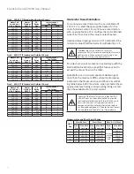
5.   Check each overload heater or electronic overload 

relay setting against the motor full-load current.

Check current transformer-operated overload 

relays to be certain that overload heaters are  

in place. Do not operate starters without 

overload protection.

6.   Check all circuit breaker trip settings and fuse ratings 

against the drawings supplied with the equipment.


a.   If trip settings must be changed, use the GE rating 

plug extractor tool (catalog number TRTOOL) to 

remove rating plugs from Spectra circuit breakers.


b.   See the startup procedure following information 

regarding instantaneous trip settings on magnetic- 

only circuit breakers.

Do not exceed the long-time and/or instanta-

neous trip settings stipulated in the National 

Electrical Code and as identified in the overload 

heater selection tables in this manual.

7.   Check all pneumatic or motor-driven timers for 

proper time-interval settings.

8.   Manually operate all branch-circuit disconnects and 

verify proper operation of disconnects and door 

interlocks.

9.   Where applicable, manually trip all circuit breakers 

to verify that operating handles move freely to the 

TRIP indicating position. With the door closed and 

latched, reset each tripped circuit breaker by pushing 

the operating handle down beyond the OFF position. 

The operating handle should move upward to the 

OFF position after the breaker has been reset. After 

the reset, turn the circuit breaker ON and then OFF 

to confirm proper operation.

10.  Visually check all units and enclosures to ensure 

that electrical spacings have not been reduced 

because of shipping and handling actions.

11.  Verify that the motor control center enclosure and 

units are grounded. 

12.  Replace all protection barriers and panels that have 

been removed during installation.

13.  Carefully clean the equipment interior with a clean 

cloth, soft brush or vacuum cleaner to remove all 

metal chips, dust, wire and other debris.

14.  After taking precautions to prevent accidental contact 

with the motor control center buswork, conduct the 

following insulation-resistance test with a 1000 Vdc 

(Megger) tester. With all disconnects in the OFF position,


• Apply voltage between all phase pairs.


• Apply voltage between each phase and ground.


 All readings should be 1 megohm minimum; typical 

values will be 50–100 megohm but may vary based 

on humidity.


 Similarly, test individual feeder and motor circuit 

wiring (field wiring) as each set of conductors is pulled 

into the motor control center, before terminating 

the conductors at either end.

15.  With all disconnects OFF, close and latch all doors 

and secure all external covers.

16.  For AFM Units, ensure that all visual indicators are 

showing “RED” to indicate “ENGAGED” stab position 

and “OPEN” shutter position.

Initial Operation of the Motor Control Center

Because of problems that may occur during

the initial energizing of the motor control

equipment, only qualified personnel should

carry out this startup procedure.

Use the following procedure for initial startup of the

motor control equipment. Be sure that the steps in the

previous section, Preparing for Initial Operation, have

been completed.

1.     Ensure that all doors are closed and latched and all 

external covers on the motor control center are  

secured. Visually check that all latches on Arc Resistant  

enclosures are engaged.

2.   Verify that all main and branch disconnects within 

the motor control center are OFF.

Summary of Contents for Evolution Series E9000

Page 1: ...EvolutionSeries E9000 Motor Control Centers User Manual DEH 40472 Rev 08 GE Energy Connections...

Page 2: ...s 16 Removal of Draw out Motor Control Center Units 18 Operating Handles Door Interlocks and Padlocking Provisions 18 Operating Handle 19 Pilot Bracket and Door 20 NEMA 3R Outdoor Enclosure Installati...

Page 3: ...on information available at the time of its publication While efforts have been made to ensure accuracy the information contained herein does not cover all details or variations in hardware and softw...

Page 4: ...ng splits Each shipping split is provided with continuous floor sills and a lifting angle Floor sills and lifting angles are field removable Each shipping split includes a continuous non removable mai...

Page 5: ...rrier For Arc Resistant design uses this same Lexan barrier with additional Metallic dead front barrier The vertical bus either 300A or 600 850 A is connected with two bolts per phase to the main bus...

Page 6: ...ous bolt sizes and joint types Bolt Size Copper Joints Aluminum Joints lb ft N m lb ft N m 5 16 18 5 9 7 12 6 5 9 9 12 3 8 16 12 16 16 22 10 15 14 20 1 2 13 30 39 41 53 25 35 34 47 5 8 11 65 80 88 108...

Page 7: ...than the lifting angle or floor sills Use two or more chains or cables to distribute the weight evenly Pinch bars pipe rollers or slings are useful implements for handling equipment but be careful to...

Page 8: ...urnished by the GE as well as all applicable contract drawings for the particular installation Pay particular attention to the location of units in the motor control center and their relations to exis...

Page 9: ...Evolution Series E9000 User Manual 8 Indoor Enclosures Elevation and Mounting 30 Deep Sections 600A to 1200A Main Bus Top Conduit Entry 30 Deep Section...

Page 10: ...t cable entry Note Bottom rear entrance should only be used with full rear accessibility Figure 6A Bottom conduit entrance details for standard 13 inch deep section low bus position Figure 6B Bottom c...

Page 11: ...of the 13 inch deep section Surface under motor control center base must be of non combustible material unless bottom covers are installed in each vertical section The overall height of the equipment...

Page 12: ...the section splits For additional gasket material orderpart number245A1888P5 Gaskets Figure 10A Type 12 and Arc Resistant gasket material between section splits NEC Work Space NEC Work Space is defin...

Page 13: ...e tops of the sections through front or rear flaps as required For Arc Resistant sections with plenum the conduit can be assembled on top of the plenum GE offers an additional pull boxforhigherconduit...

Page 14: ...e in Chapter 5 Exhaust Fan InstallationforULType 12 Enclosure and Arc Resistant Vented Fan Shields Filter Assembly UL Type 12 Fan Assembly Arc Resistant VFD Fan Shield Figure 16B Exhaust fan for UL Ty...

Page 15: ...the cable insulation on any sharp edges such as steel work or screws Where access to the rear of the section is available cables can be brought into the space behind the vertical bus and brought forw...

Page 16: ...ug is provided in each draw out combination starterunitforterminating a motor frame grounding wire For larger starters the lug is mounted on the horizontal ground bus 5 Use cord or plastic ties to sec...

Page 17: ...cks are mounted on a metal rail located at the bottom of the unit as shown in Figure 22 The terminal block easily slides into position from either side of the mounting rail Figure 22 Mounting the term...

Page 18: ...sure that all screw terminals are tight all foreign material and packing are removed and the insulating barriers are secure 7 The unit disconnect must be in the OFF position before the unit can be ins...

Page 19: ...nadvertent contact Failure to observe this precaution can result in serious injury or death 5 Turn the latches at the top and bottom of the unit a quarter turn counterclockwise to release the unit The...

Page 20: ...Size 5 FVNR 125 36 CAUTION should be used when removing or installing units considerthe weight intable above Two persons may be required orthe assistance of a lifting devices See page 21 for suggested...

Page 21: ...er Note that the left module right rear cover has a flange that will be underneath the removed covered with it is replaced This provides an overlapping connection in the rear of the two spliced module...

Page 22: ...Evolution Series E9000 User Manual 21...

Page 23: ...at operating handles move freely to the TRIP indicating position With the door closed and latched reset each tripped circuit breaker by pushing the operating handle down beyond the OFF position The op...

Page 24: ...nected during startup 8 Adjust instantaneous settings on magnetic onlycircuit breakers and or fuse sizes and overload heater selectionsto achieve propermotorand branch circuit protection See NEC Artic...

Page 25: ...hown Figure 38 Adjust the pilot device bracket and extension bubble lip so it enters in between the keeper bracket and inside of the door Figure 39 Close the door completely and turn the 1 4 turn latc...

Page 26: ...or interlocks for proper operation 10 Check all indicating lights and replace as required 11 If fuse replacement is necessary always install the same type and rating as the fuses furnished with the mo...

Page 27: ...ables not required for accessories only 4 Remove the toggle holding plate toggle needs to be in the ON position UP 5 Remove the top four screws in top plate holding the breaker assembly not required f...

Page 28: ...peed GEH 4806 NEMA Size 3 FVR 2 Speed GEH 4807 NEMA Size 4 FVR 2 Speed GEH 4839 NEMA Size 5 FVR 2 Speed GET 6915A Tech Info Contact Appearance Arc Flash Mitigation Units DEI 007 Remote Racking System...

Page 29: ...keted 1 HG heavy gasketed 2 3R or 12 6 Power supply characteristics Voltage Number of phases Frequency in Hz 7 Control power voltage and frequency in Hz 8 Nameplate designation and title 9 Motor chara...

Page 30: ...70 C379A 22 6 23 9 C273B 3 71 4 06 C419A 24 0 26 3 C303B 4 07 4 47 C466A 26 4 27 0 C330B 4 48 4 95 C526A Size 2 Standard and Ambient Comp Motor Full Load Amps 3 Ph 3 Heater Heater Number CR123 Motor...

Page 31: ...f heater full load current multiplied by 1 25 Circuit breaker tripping may be an indication that a fault current has been interrupted To provide continued protection against fire or shock hazard exami...

Page 32: ...1 C125B 15 3 6 11 2 12 1 C137B 15 3 7 11 2 12 1 C137B 30 LO 2 12 2 13 0 C151B 15 4 8 12 2 13 0 C151B 30 LO 2 13 1 15 5 C163B 30 1 3 15 6 16 8 C180B 30 1 4 16 9 18 0 C198B 30 2 5 18 1 19 7 C214B 30 2 5...

Page 33: ...9 130 F161C 150 2 6 Size 5 Standard and Ambient Comp Motor Full Load Amps 3 Ph 3 Heater Heater Number CR123 TEC TECL Rating Mag Break Trip Setting Rec Max 106 115 C592A 550 1670 2 6 116 125 C630A 550...

Page 34: ...8 81 9 27 C104B 15 3 5 9 28 9 99 C113B 20 2 4 10 0 11 1 C125B 20 2 5 11 2 12 1 C137B 20 3 5 12 2 13 0 C151B 20 3 5 13 1 15 5 C163B 20 4 6 15 6 16 8 C180B 25 3 5 16 9 18 0 C198B 25 3 6 18 1 19 7 C214B...

Page 35: ...4C 150 3 5 93 5 105 0 F118C 150 3 5 106 0 114 0 F133C 150 3 5 115 0 128 0 F149C 150 4 6 129 0 130 0 F161C 150 4 6 Size 4 Standard Motor Full Load Amps 3 Ph 3 Heater Heater Number CR123 SE Rating Plug...

Page 36: ...with a service factor of 1 0 multiply the motor full load current by 0 9 and use this value to select heaters Overload relay tripping current in 40 C ambient is the minimum value of full load current...

Page 37: ...20 1 21 5 C228B 601 21 6 22 5 C250B 601 22 6 23 9 C273B 601 24 0 26 3 C303B 601 26 4 27 0 C330B 601 Size 2 Standard and Ambient Comp Motor Full Load Amps 3 Ph 3 Heater Heater Number CR123 Maximum Fuse...

Page 38: ...70 6 F848B 2501 70 7 76 3 F914B 2751 76 4 88 7 F104C 3001 88 8 93 4 F114C 3501 93 5 105 F118C 3501 106 114 F133C 4001 115 128 F149C 4001 129 131 F161C 4001 132 135 F174C 4001 Size 5 300 15CT Standard...

Page 39: ...4 78 5 06 C630A ElectronicOverloadforCircuitBreakerandFused Controllers The tripping current is 120 of the dial setting For continuous rated motors with a service factor of 1 15 to 1 25 set the dial...

Page 40: ...4 0 CR324GXN 400 600 51 65 to 129 9 CR324GXP 51 130 to 270 CR324GXQ 62 130 to 259 9 CR324HXS 600 Class L 1200 1 300 15 CT s 2 800 5 CT s IECStyleOverloadRelays C2000ContactorCLNCJTypeRTOverloadRelayfo...

Page 41: ...r Cat No FLA Range Lug Wire Size Torque in lbs Class 10 Class 20 LAR08AJ RTN2B NA 15 1 19 10 3 AWG 50 LAR10AJ RTN2C NA 19 1 25 10 3 AWG 50 RTN2D RT22D 25 1 32 10 3 AWG 50 RTN2E RT22E 32 1 43 10 3 AWG...

Page 42: ...Evolution Series E9000 User Manual 41 Notes...

Page 43: ...42 Evolution Series E9000 User Manual Notes...

Page 44: ...eneral Electric Company 2017 General Electric Company Information provided is subject to change without notice All values are design or typical values when measured under laboratory conditions DEH 404...

Reviews: