3300/03 System Monitor Operation Manual
12
10. Keyphasor OPERATIONAL TEST
The following test procedure for Keyphasor
®
transducer 1 is also applicable for testing
Keyphasor
®
transducers 2 through 4.
The machine associated with the Keyphasor
®
transducer under test should be running during
this procedure. If the machine is not turning, simulate the operating machinery input at
approximately the same frequency as the shaft rotating speed, with a function generator or TK3
test kit.
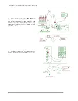
1. Measure Keyphasor
®
1
power at the
KPH1PWR
terminal on the power input
module (PIM). If -VT is -24 V,
the voltage should read
between -23.2 and -24.2
Vdc. If -VT is -18 V, the
voltage should read
between -17.40 and -18.30
Vdc.


