Chapter 3. Inserting T9 Transducers into the Pipe
22
Model T9 Ultrasonic Flow Transducer Installation Guide
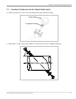
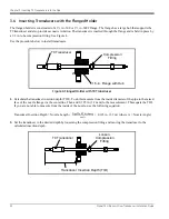
3.4 Inserting Transducers with the Flanged Holder
The flanged holder is constructed of a 1
½
in.-300 or 1
½
in.-600# flange. The flange has a large hub that supports the
T9 transducer and also provides acoustic isolation. The transducer is inserted through the flange and is held in place by
a 1/2 in. tube compression fitting. See Figure 4.
Use the procedure below to install transducers.
Figure 4: Flanged Holder with T9 Transducer
1.
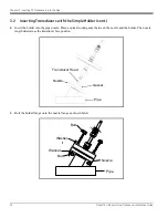
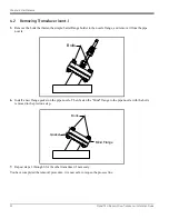
Calculate the transducer insertion depth (TID). To do this measure from the inside diameter of the pipe to the raised
face of the nozzle flange via the centerline. Then add 0.125 in. (3.2 mm) to the measurement. This equals the TID.
If you are not able to measure from the inside of the nozzle, use the following equation:
Transducer Insertion Depth = Nozzle
+ 0.125 in. (3.2 m) (where A = Nozzle Angle)
2.
Set the transducer to the desired depth by loosening the compression fitting and moving the transducer to the
calculated insertion depth.
T9 Transducer
1.5-in. Flange with Hub
Compression
Fitting
PipeWallThickness
A
cos
----------------------------------------------------
T9 Transducer
Loosen
Compression
Fitting
Transducer Insertion Depth (TID)

