5.1.6 Logic Controller Programming
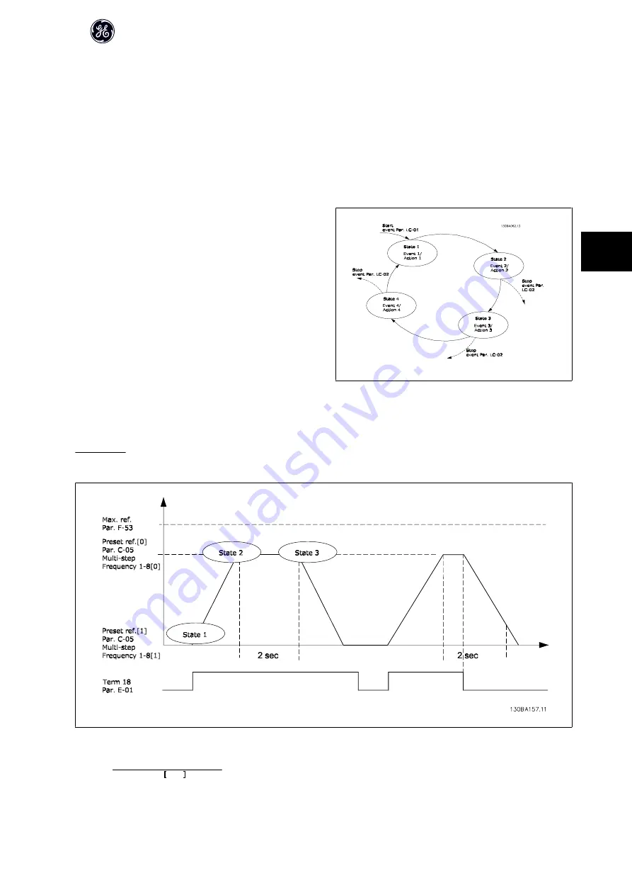
The Logic Controller (LC) is essentially a sequence of user defined actions (see par. LC-52
Logic Controller Action
) executed by the LC when the associated user
defined
event
(see par. LC-51
Logic Controller Event
) is evaluated as TRUE by the LC.
Events
and
actions
are each numbered and are linked in pairs called states. This means that when
event [1]
is fulfilled (attains the value TRUE),
action [1]
is executed.
After this, the conditions of
event [2]
will be evaluated and if evaluated TRUE,
action [2]
will be executed and so on. Events and actions are placed in array parameters.
Only one
event
will be evaluated at any time. If an
event
is evaluated as FALSE, nothing happens (in the LC) during the present scan interval and no other
events
will be evaluated. This means that when the LC starts, it evaluates
event [1]
(and only
event [1]
) each scan interval. Only when
event [1]
is evaluated TRUE, the LC
executes
action [1]
and starts evaluating
event [2]
.
It is possible to program from 0 to 20
events
and
actions
. When the last
event /
action
has been executed, the sequence starts over again from
event [1] /
action [1]
. The illustration shows an example with three
events / actions
:
5.1.7 LC Application Example
One sequence 1:
Start – accel – run at reference speed 2 sec – decel and hold shaft until stop.
Set the accel/decel times in par. F-07
Accel Time 1
and par. F-08
Decel Time 1
to the wanted times
tramp
=
tacc
×
nnorm
(
par
.
P
−
06)
ref
RPM
AF-600 FP Design Guide
97
5
Summary of Contents for AF-600 FP Series
Page 11: ...AF 600 FP Design Guide 10 2...
Page 45: ...AF 600 FP Design Guide 44 3...
Page 51: ...Do not combine low voltage parts and PELV systems AF 600 FP Design Guide 50 3...
Page 58: ...4 How to Install AF 600 FP Design Guide 57 4...
Page 95: ...AF 600 FP Design Guide 94 5...
Page 102: ...5 1 11 Fixed Variable Speed Pump Wiring Diagram AF 600 FP Design Guide 101 5...
Page 105: ...AF 600 FP Design Guide 104 6...


