CHAPTER 3: INTERFACES
SOFTWARE SETUP
350 FEEDER PROTECTION SYSTEM – QUICKSTART GUIDE
79
4.
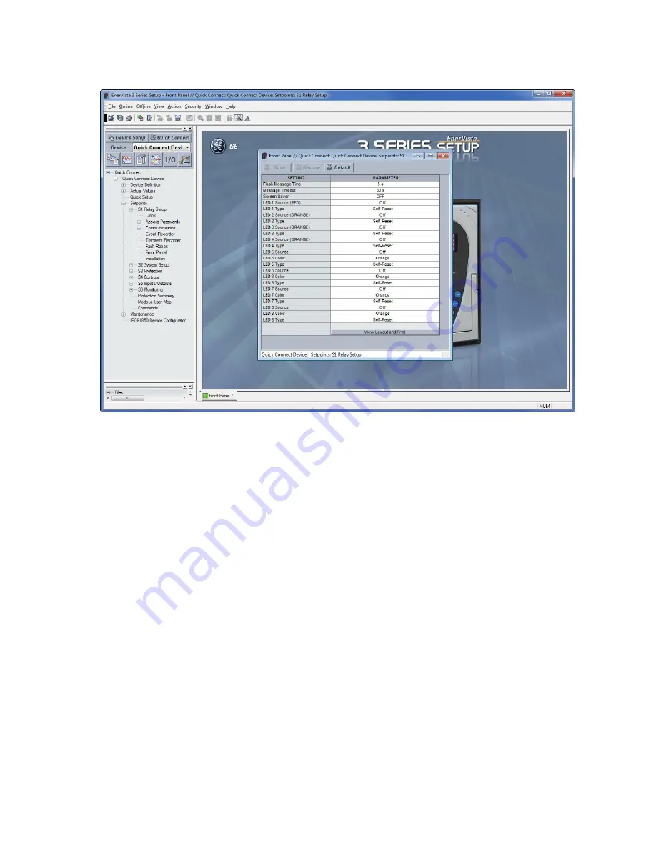
The Front Panel settings window opens with a corresponding status indicator on the
lower left of the EnerVista 3 Series Setup window.
5.
If the status indicator is red, verify that the serial, USB, or Ethernet cable is properly
connected to the relay, and that the relay has been properly configured for
communications (steps described earlier).
The Front Panel settings can now be edited, printed, or changed. Other setpoint and
command windows can be displayed and edited in a similar manner. "Actual Values"
windows are also available for display. These windows can be arranged, and resized at
will.
Working with setpoints and setpoint files
Engaging a device
The EnerVista 3 Series Setup software may be used in on-line mode (relay connected) to
directly communicate with a relay. Communicating relays are organized and grouped by
communication interfaces and into sites. Sites may contain any number of relays selected
from the product series.
Entering setpoints
The System Setup page will be used as an example to illustrate the entering of setpoints. In
this example, we will be changing the voltage sensing setpoints.
1.
Establish communications with the relay.
2.
Select the
Setpoint > System Setup > Voltage Sensing
menu item.
3.
Select the Bus VT Secondary setpoint by clicking anywhere in the parameter box. This
will display three arrows: two to increment/decrement the value and another to
launch the numerical keypad.


