background image

CHAPTER 2: INSTALLATION

MECHANICAL INSTALLATION

350 FEEDER PROTECTION SYSTEM – QUICKSTART GUIDE

39

Avoid surface temperatures above 70 °C or 158 °F to prolong the life of the fiber.

Secure all sensor fibers (loosely but securely) away from any moving parts.

Point sensor 

installation

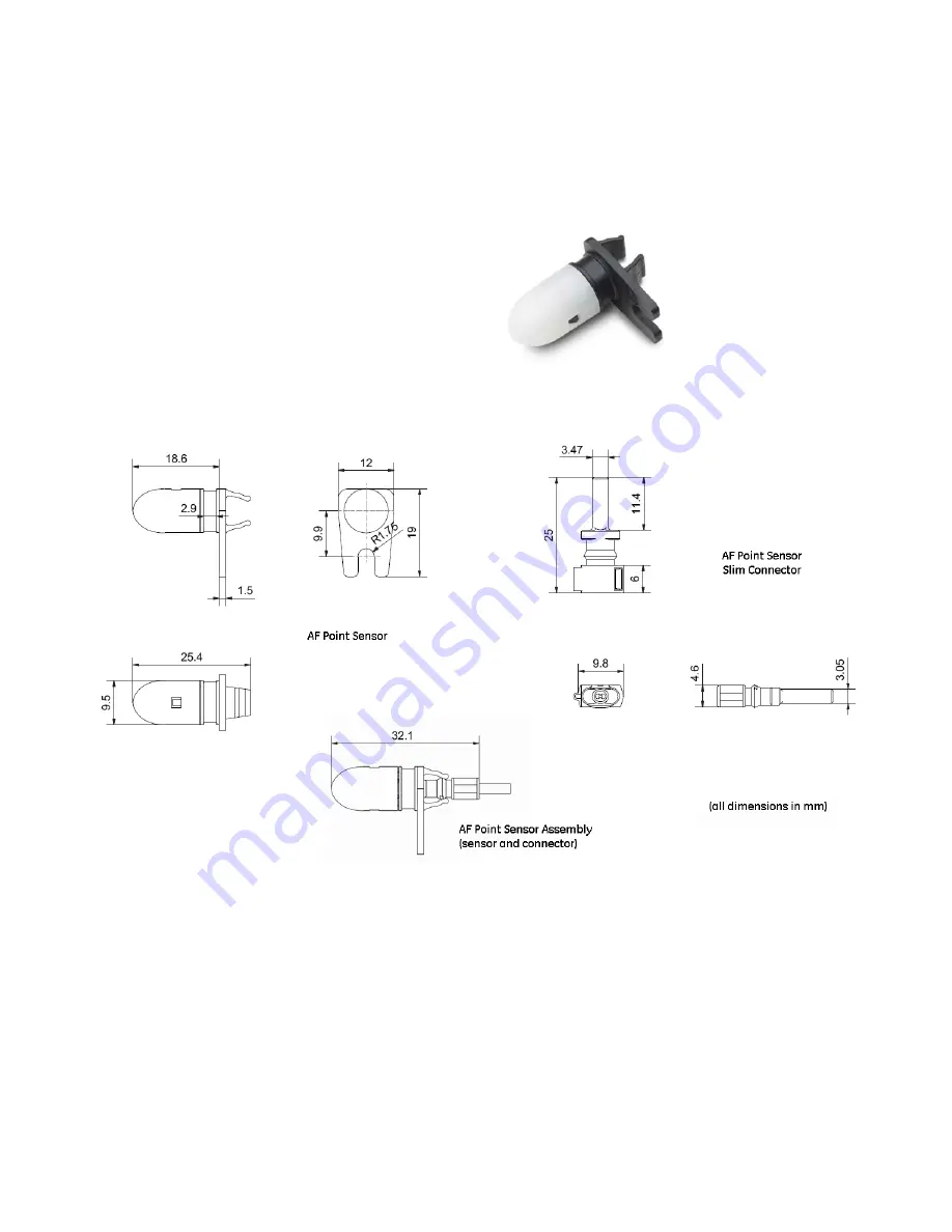
Figure 2-15: Arc flash point sensor without sensor fiber connected

Figure 2-16: Point sensor and slim connector dimensions

Summary of Contents for 350-A9

Page 1: ...092 AJ 350 Feeder Protection System Feeder protection and control GE Grid Solutions Quick Start Guide 350 revision 2 3x Manual P N 1601 9092 AJ GE publication code GEK 113535S LISTED 52TL IND CONT EQ...

Page 2: ...arranty htm For products shipped before 1 October 2013 the standard 24 month warranty applies Repairs The firmware and software can be upgraded without return of the device to the factory For issues n...

Page 3: ...uipment off prior to removing the power connections could expose you to dangerous voltages causing injury or death All recommended equipment that should be grounded and must have a reliable and un com...

Page 4: ...if not avoided could result in minor or moderate injury Note Indicates practices not related to personal injury For further assistance For product support contact the information and call center as f...

Page 5: ...28 Mounting using the S1 S2 MDP IAC or SR735 adapter plate 32 Drawout unit withdrawal and insertion 35 IP20 Cover optional 36 Arc flash sensors 37 Sensor fiber handling storage 38 Point sensor install...

Page 6: ...setpoint files 79 Engaging a device 79 Entering setpoints 79 Setting programmable LEDs 81 File support 82 Using setpoint files 82 Downloading and saving setpoint files 83 Adding setpoint files to the...

Page 7: ...selection of protocols such as Modbus DNP3 0 IEC 60870 5 103 60870 5 104 IEC61850 GOOSE OPC UA the 350 relay is the best in class for MCCs and PCCs SCADA and inter relay communications The 350 relay...

Page 8: ...ent false zero crossings Sampling is synchronized to the Va x voltage zero crossing which results in better co ordination for multiple 350 relays on the same bus Phasors Transients and Harmonics Curre...

Page 9: ...ertz 25 RSYN1 Synchrocheck 27_1 psseqPTUV1 Positive Sequence Undervoltage 27P phsPTUV1 phsPTUV2 phsPTUV3 phsPTUV4 Phase Undervoltage 27X auxPTUV1 Auxiliary Undervoltage 32 PDOP1 PDOP2 Directional Powe...

Page 10: ...PTUF4 Underfrequency 86 Lockout CLP Cold Load Pickup VTFF 60VTS Voltage Fuse Failure MMXU1 Voltage Energy Power Metering Description 2nd Harmonic Blocking Arc Flash Detector Ambient Temperature Breake...

Page 11: ...Outputs 32 Description ACTUAL VALUES COMMANDS SETPOINTS MAINTENANCE ACTUAL VALUES A1 STATUS A2 METERING A3 RECORDS A4 TARGET MESSAGES QUICK SETUP RELAY STATUS NOMINAL FREQUENCY PH CT PRIMARY PH CT SE...

Page 12: ...50N 2 51P 1 51G SG 1 51N 1 M Advanced configuration Extended 51_2 or 46 1 50_2 1 or 46 1 I1 I2 46BC Control N CLP Lockout 86 C CLP 50BF Lockout 86 Autoreclose 79 Other Optionse e CLP 79 and 50BF are n...

Page 13: ...to minimize exposure to ambient light when running the sensor fiber between cabinets A duplex sensor fiber extension connects the relay to the loop sensor and can be gently pulled apart to connect to...

Page 14: ...Neutral and Ground Directional Overcurrent Protection 67N 1 67G SG 1 60CTS M Voltage Power and Energy Metering 60CTS R Phase Neutral and Ground Directional Overcurrent Protection 67P 1 67N 1 67G SG 1...

Page 15: ...o 1 00 x CT in steps of 0 01 x CT Maximum operating positive current 0 05 to 5 00 x CT in steps of 0 01 x CT Pickup level 20 0 to 100 0 in steps of 0 1 Dropout level 97 to 98 of the pickup level Picku...

Page 16: ...r for values greater than 1 1 x pickup PHASE NEUTRAL GROUND NEGATIVE SEQUENCE TIME OVERCURRENT 51P 51N 51G 51_2 Pickup Level 0 05 to 20 00 x CT in steps of 0 01 x CT Dropout Level 97 of Pickup I 1 x C...

Page 17: ...Voltage Quadrature Voltage ABC phase sequence Vbc Vca Vab CBA phase sequence Vcb Vac Vba Polarizing voltage threshold 0 05 to 1 25 x VT in steps of 0 01 MTA Maximum Torque Angle From 0 to 359 in step...

Page 18: ...h cases THERMAL OVERLOAD 49 Current RMS current max Ia Ib Ic Pickup Accuracy per current inputs Timing Accuracy See graph below Figure 1 5 The graph shows the trip time error with respect to the ratio...

Page 19: ...05 Hz Time Delay 0 1 to 600 0 s in steps of 0 01 Time Delay Accuracy 0 to 6 cycles Time Delay selected Operate Time Typically 10 cycles 0 1Hz s change Level Accuracy 0 03 Hz ARC FLASH HS PHASE GROUND...

Page 20: ...pout Alarm Data AC input channels Contact input state Contact output state Virtual input state Logic element state Data storage RAM battery backed up FAULT RECORDER Number of records 1 Content Date an...

Page 21: ...OR XNOR Pickup Dropout timers Pickup timer 0 to 60000 ms in steps of 1 ms Dropout timer 0 to 60000 ms in steps of 1 ms BREAKER CONTROL Operation Asserted Contact Input Logic Element Virtual Input Manu...

Page 22: ...ee the specifications for phase and ground current inputs Operate Time 30 ms at 60 Hz 35 ms at 50 Hz BREAKER TRIP COUNTER Trip Counter Limit Pickup 1 to 10000 in steps of 1 LOCKOUT Function Latch Trip...

Page 23: ...of 0 1 kVar Apparent Power Pickup Level 0 1 to 300000 0 in steps of 0 1 kVA Dropout Level 96 98 of Pickup level Level Accuracy 2 current demand only Inputs CONTACT INPUTS Inputs 10 Selectable thresho...

Page 24: ...range 50 to 240 V VT ratio 1 0 to 5000 0 in steps of 0 1 Nominal frequency 50 60 Hz Relay burden 0 25 VA at 120 V Accuracy 1 0 throughout range Voltage withstand 260 VAC continuous Outputs ARC FLASH...

Page 25: ...rry for 1 s 10 A Break DC resistive 300 V 6 A Break DC inductive L R 40ms 300 V 6 A Ratings per UL Certification Break 24 VDC 1 A Pilot Duty 48 VDC 0 5 A Pilot Duty 125 VDC 0 3 A Pilot Duty 250 VDC 0...

Page 26: ...ve 720 VA 240 VAC Pilot duty A300 Break AC resistive 250 VAC 10 A Ratings per UL Certification Break AC resistive 250 VAC 10 A GEN USE Continuous Current 10 A TRIP CLOSE SEAL IN Relay 1 trip seal in 0...

Page 27: ...r type 100 MB Multi mode Wavelength 1300 nm Connector MTRJ Protocol Modbus TCP DNP3 0 IEC 60870 5 104 IEC 61850 GOOSE IEC 61850 OPC UA PRP HSR Transmit power 20 dBm Receiver sensitivity 31 dBm Power b...

Page 28: ...m Voltage interruption and Ripple DC IEC 60255 26 IEC 60255 4 11 15 ripple 200ms interrupts Radiated Conducted Emissions CISPR11 CISPR22 IEC 60255 26 Section 7 1 2 7 1 3 Class A Sinusoidal Vibration...

Page 29: ...ross 4 0 kg 8 6 lbs DRAWOUT UNIT Weight net 3 9 kg 8 6 lbs Weight gross 5 0 kg 11 0 lbs Applicable Council Directive According to Low voltage directive 2014 35 EU CE compliance EMC Directive 2014 30 E...

Page 30: ...ING ENVIRONMENT Ambient temperatures Storage Shipping 40o C to 85o C Operating 40o C to 60o C Humidity Operating up to 95 non condensing 55o C As per IEC60068 2 30 Variant 2 6 days Altitude 2000 m max...

Page 31: ...tion GE Grid Solutions Installation Mechanical installation This section describes the mechanical installation of the 350 system including dimensions for mounting and information on module withdrawal...

Page 32: ...INSTALLATION Dimensions The dimensions of the 350 are on the following pages Additional dimensions for mounting and panel cutouts are shown in the following sections Figure 2 1 350 dimensions Drawout...

Page 33: ...INSTALLATION MECHANICAL INSTALLATION 350 FEEDER PROTECTION SYSTEM QUICKSTART GUIDE 27 Figure 2 2 350 dimensions Non drawout unit 6 23 158 2mm 7 98 202 7mm 1 47 37 3mm 7 88 200 2mm 6 82 173 2mm 3 96 1...

Page 34: ...th America 1 800 547 8629 www gegridsolutions com multilin 650 Markland Street Markham ON Canada L6C 0M1 MFG Date Mar 11 2017 Feeder Protection System g Model 350 E P1 G1 H E S N M 2E N N Serial Numbe...

Page 35: ...T GUIDE 29 Figure 2 4 Standard panel mounting Drawout Figure 2 5 Standard Panel mounting Non drawout 8 32X3 8IN P HD PHIL BLK GE PART 1408 0306 QTY 8 TIGHTENING TORQUE 15 IN LB 8 32 x 3 8 P HD PHIL BL...

Page 36: ...375 or 3 to the unit captive or non drawout using 4 screws see above 2 Mount the combination of unit and collar to the panel using 4 screws as shown above Figure 2 7 Mounting tabs optional 1 From the...

Page 37: ...abs outward to about 90 These tabs are located on the sides of the case and appear as shown above The relay can now be inserted and can be panel wired Figure 2 8 Panel cutout dimensions 5 350 0 010 13...

Page 38: ...EW MAKE SURE THE MOUNTING SCREWS GE PART 1410 0112 DO NOT PENETRATE THROUGH THE ADAPTER PLATE FRONT SURFACE MOUNT THE CAPTIVE UNIT WITH THE ADAPTER PLATE SLIDE AND LOCK THE DRAWOUT UNIT INTO THE CAPTI...

Page 39: ...ECHANICAL INSTALLATION 350 FEEDER PROTECTION SYSTEM QUICKSTART GUIDE 33 Figure 2 10 Non drawout Adapter plate mounting 350 ADAPTER PLATE FOR SR735 11 000 279 4 mm 8 000 203 2 mm 6 123 155 5 mm 9 750 2...

Page 40: ...MECHANICAL INSTALLATION CHAPTER 2 INSTALLATION Figure 2 11 Panel cutout dimensions 5 350 0 010 135 9 mm 0 25mm 4 100 0 010 104 1 mm 0 25 mm 0 200 5 1 mm 6 900 0 010 175 3 mm 0 25 mm 6 000 0 010 152 4...

Page 41: ...insertion diagram KEEP THE HANDLE IN ITS ROTATED POSITION UNTIL THE DRAW OUT UNIT IS INSERTED COMPLETELY PUSH THE HANDLE DOWN AND TIGHTEN THE SCREW UNTIL THE HANDLE IS PARALLEL WITH THE FRONT PANEL SU...

Page 42: ...ing order A Remove the 2 mounting screws near letters A and C of label ABC item 2 and mount 2 standoffs B Remove the 2 mounting screws near the letters B and E of label ABCDE item 3 and mount 2 stando...

Page 43: ...s product uses optical electronic devices line or point sensors to sense arc flash fault conditions It is recommended to follow proper housekeeping measures establish a regularly scheduled preventive...

Page 44: ...d if twisted bent or clamped tightly during installation Do not bend sensor fiber sharply or with a radius of less than 35 mm 1 3 inches Sharp bends can damage the fiber Do not pull or tug loops of se...

Page 45: ...oid surface temperatures above 70 C or 158 F to prolong the life of the fiber Secure all sensor fibers loosely but securely away from any moving parts Point sensor installation Figure 2 15 Arc flash p...

Page 46: ...sor fiber handling guidelines above Sensor fiber should be held in place loosely for the best long term performance Avoid over tightening ties which may deform or break the sensor fiber General instal...

Page 47: ...tive grommets when routing sensor fiber through metal walls 4 Mount the point sensor using either a cable tie mount or through hole mount as detailed below 5 Reconnect the slim connector to the point...

Page 48: ...ough hole mount Figure 2 20 AF point sensors connected to 350 relay Make sure there is no dirt or dust inside the point sensor or on the surface because it reduces the capturing efficiency of the devi...

Page 49: ...iber has a single connector on either end The sensor fiber extension has a duplex connector on one end two single connectors on the other end and comes with two single bulkhead connectors Both come in...

Page 50: ...TION SYSTEM QUICKSTART GUIDE MECHANICAL INSTALLATION CHAPTER 2 INSTALLATION Figure 2 22 Duplex connector dimensions point sensor and sensor fiber extension for loop sensor Figure 2 23 Single bulkhead...

Page 51: ...loop remain close enough together to be reached by the sensor fiber extension If needed gently pull apart the duplex sensor fiber extension from the end with two single connectors being careful not to...

Page 52: ...SYSTEM QUICKSTART GUIDE ELECTRICAL INSTALLATION CHAPTER 2 INSTALLATION Electrical installation This section describes the electrical installation of the 350 system including typical wiring diagrams an...

Page 53: ...EEDER BUS Vts 52 E5 D5 E6 D6 E7 D7 E8 D8 IA IA IB IB IC IC IG IG FEEDER Cts CONNECT AUX_VT AS REQUIRED VOLTAGE INPUTS WYE VT CONNECTION E9 D9 E10D10E11D11E12D12 VA VA VB VB VC VC VX VX 7 CRITICAL FAIL...

Page 54: ...Y 6 AUXILIARY 2 CLOSE 1 TRIP OPEN DELTA VT CONNECTION E9 D9 E10D10E11D11 OPTIONAL DIRECTION OF POWER FLOW FOR POSITIVE WATTS POSITIVE DIRECTION OF LAGGING VARs Front Panel Rear Panel 350 Feeder Protec...

Page 55: ...TE When installing two lugs on one terminal both lugs should be right side up as shown in the picture below This is to ensure the adjacent lower terminal block does not interfere with the lug body Fig...

Page 56: ...50 350 FEEDER PROTECTION SYSTEM QUICKSTART GUIDE ELECTRICAL INSTALLATION CHAPTER 2 INSTALLATION Figure 2 30 INCORRECT INSTALLATION METHOD lower lug reversed...

Page 57: ...SE C VT AUX VT PHASE A CT PHASE B CT PHASE C CT GND CT PHASE A VT PHASE B VT PHASE C VT AUX VT IRIG B IRIG B RS485 RS485 RS485 COM CHASSIS GND RESERVED RESERVED POWER SUPPLY CHASSIS GND TRIP COM CLOSE...

Page 58: ...type copper Phase sequence and transformer polarity For correct operation of the relay features the user must follow the instrument transformer polarities shown in the Typical Wiring Diagram Note the...

Page 59: ...tomatically calculates the neutral residual current from the sum of the three phase current phasors The following figures show three possible ground connections or three possible sensitive ground conn...

Page 60: ...nce CT is recommended Figure 2 34 Zero sequence core balance CT installation SOURCE 898730A1 CDR A B C USED FOR POLARIZING GROUND CURRENT INPUT 350 PHASE CURRENT INPUTS A B C GROUND CURRENT INPUT WITH...

Page 61: ...Input The Aux VT input channel can be connected for either phase neutral voltage Van Vbn Vcn or for phase phase voltage Vab Vbc Vca as shown below Figure 2 35 Auxiliary VT connections Control power C...

Page 62: ...uits to ground or else relay hardware may be damaged A wet contact has one side connected to the positive terminal of an external DC power supply The other side of this contact is connected to the req...

Page 63: ...A output relays 1 Trip and 2 Close The voltage monitor is connected across each of the two Form A contacts and the relay effectively detects healthy current through the circuit In order to do this an...

Page 64: ...igure 2 38 Trip and Close circuits with no voltage monitoring NOTE NOTE All AUX contacts are shown when the breaker is open Figure 2 39 Trip and close circuits with voltage monitoring V A2 B3 A3 Trip...

Page 65: ...als of each RS485 port are tied together and grounded only once at the master or at the 350 Failure to do so may result in intermittent or failed communications The source computer PLC SCADA system sh...

Page 66: ...modulated AM form The type of form is auto detected by the 350 relay Third party equipment is available for generating the IRIG B signal this equipment may use a GPS satellite system to obtain the ti...

Page 67: ...otection System Interfacing via the relay keypad and display Interfacing via the EnerVista 3 Series Setup software This section provides an overview of the interfacing methods available with the 350 u...

Page 68: ...S Front control panel interface Figure 3 1 350 Feeder Protection System Front Panel Non programmable LEDs ENTER MENU ESCAPE RESET 898351A1 cdr USB GE Multilin 350 Feeder Protection System IN SERVICE T...

Page 69: ...tus indicators control keys and a USB program port The display and status indicators show the relay information automatically The control keys are used to select the appropriate message for entering s...

Page 70: ...are organized into a Main Menu pages and sub pages There are four main menus labeled Actual Values Quick Setup Setpoints and Maintenance Pressing the MENU key followed by the MESSAGE key scrolls throu...

Page 71: ...etpoint values into memory to complete the change The MESSAGE key can also be used to enter sub pages but not to store altered setpoints The ESCAPE key is also dual purpose It is used to exit the sub...

Page 72: ...utput relay The LED will reset by initiating a reset command from either the RESET pushbutton Breaker Control or communications in all cases after the fault condition has cleared ALARM Orange This LED...

Page 73: ...eaker Control or communications in all cases after the fault condition has cleared ALARM Orange This LED will flash upon detection of an alarm condition with element functions selected as alarm The LE...

Page 74: ...e format of a typical Target Message Figure 3 5 Typical target message Example of a Phase IOC1 operation phase A Phase IOC1 function Trip Cause Function The first line contains information of the caus...

Page 75: ...ble is connected check cable functionality i e physical damage or perform continuity test ensure IRIG B receiver is functioning and check input signal level it may be less than specification If none o...

Page 76: ...rming the configured sequence MAINTENANCE ALERT High Ambient Temperature No The ambient temperature is above 80o C Every 1 hour Increase ventilation to the surroundings MAINTENANCE ALERT Daughter Erro...

Page 77: ...p Software interface The Quick Setup window allows you to configure important settings from different screens in the relay by adding them to a common window Quick Setup window options are available fo...

Page 78: ...o a PC and communications are enabled the 350 can be programmed from the setting screens In addition measured values status and trip messages can be displayed with the actual value screens Hardware an...

Page 79: ...from the Web or CD and automatically start the installation process A status window with a progress bar will be shown during the downloading process 7 Select the complete path including the new direct...

Page 80: ...icate from your computer to the 350 Relay using the USB port 10 Plug the USB cable into the USB port on the 350 Relay then into the USB port on your computer 11 Launch EnerVista 3 Series Setup from La...

Page 81: ...ultilin F485 converter will be required Refer to the F485 manual for additional details To configure the relay for Ethernet communications see Configuring Ethernet Communications below 1 Install and s...

Page 82: ...ay below to begin communications Using the Quick Connect feature The Quick Connect button can be used to establish a fast connection through the front panel USB port of a 350 relay or through the Ethe...

Page 83: ...oftware available from the GE EnerVista CD See the previous section for the installation procedure 2 Click on the Device Setup button to open the Device Setup window and click the Add Site button to d...

Page 84: ...top left corner of the main EnerVista 3 Series Setup window The 350 Site Device has now been configured for Ethernet communications Proceed to the following section to begin communications Connecting...

Page 85: ...e arranged and resized at will Working with setpoints and setpoint files Engaging a device The EnerVista 3 Series Setup software may be used in on line mode relay connected to directly communicate wit...

Page 86: ...setpoints requiring non numerical pre set values e g 3 Phase voltage connection below clicking anywhere within the setpoint value box displays a drop down selection menu arrow Select the desired valu...

Page 87: ...bel This opens a Quick Navigation window 4 Select a Type for the LED Latched or Self Reset and a Color if applicable 5 Repeat this process for all programmable LED Source Type and Color parameters 6 I...

Page 88: ...andling changes to relay settings In off line mode relay disconnected to create or edit relay settings files for later download to communicating relays Directly modifying relay settings while connecte...

Page 89: ...ned and configured as shown in Connecting EnerVista 3 Series Setup to the Relay above 2 Select the desired device from the site list 3 Select the Online Read Device Settings from Device menu item or r...

Page 90: ...in back compatibility of setpoint files For current order codes refer to the GE Multilin website at http www gegridsolutions com multilin NOTE NOTE Refer to the 3 Series Retrofit Instruction Manual fo...

Page 91: ...ies menu item and note the File Version of the setpoint file If this version is different from the Firmware Revision noted in step 2 select a New File Version that matches the Firmware Revision from t...

Page 92: ...eview Settings File is identical to the steps above 5 Setpoint lists can be printed in the same manner by right clicking on the desired file in the file list or device in the device list and selecting...

Page 93: ...ersion 3 Right click on the selected file and select the Write Settings File to Device item 4 Select the target relay from the list of devices shown and click Send If there is an incompatibility an er...

Page 94: ...nts Files for details on saving relay setpoints to a file Loading new relay firmware Loading new firmware into the 350 flash memory is accomplished as follows 1 Connect the relay to the local PC and s...

Page 95: ...t be in service and will require setpoint programming To communicate with the relay the communication settings may have to be manually reprogrammed When communications is established the saved setpoin...

Page 96: ...urve Editor screen is shown below The Operate Curves are displayed which can be edited by dragging the tips of the curves A Base curve can be plotted for reference to customize the operating curve The...

Page 97: ...ed select the Actual Values A3 Records Transient Records menu item to open the Transient Recorder Viewer window Click on Trigger Waveform to trigger a waveform capture Waveform file numbering starts w...

Page 98: ...r press the Preference button to open the COMTRADE Setup page in order to change the graph attributes Display graph values at the corresponding cursor line Cursor lines are identified by their colors...

Page 99: ...ect other options as required by checking the appropriate boxes Click OK to store these graph attributes and to close the window The Waveform Capture window will reappear based on the selected graph a...

Page 100: ...settings from Grouped Elements Control Elements and Maintenance screens Protection Summary Screen allows the user to view the output relay assignments for the elements modify the output relay assignme...

Page 101: ...CHAPTER 3 INTERFACES SOFTWARE SETUP 350 FEEDER PROTECTION SYSTEM QUICKSTART GUIDE 95...

Page 102: ...to be used the user must first change the Master Password from the initial Null setting this can only be done over communications not from the front panel keypad The new Master Password must be 8 to 1...

Page 103: ...hanged from the initial NULL value to a valid one Local Passwords must be 3 to 10 characters in length 6 If any Remote password has never been set that level will not be attainable except when logged...

Page 104: ...98 350 FEEDER PROTECTION SYSTEM QUICKSTART GUIDE SOFTWARE SETUP CHAPTER 3 INTERFACES...

Page 105: ...current elements can be easily set NOTE NOTE Ensure the relay is in Relay Ready state before using Quick Setup Figure 4 1 Quick Setup menu ACTUAL VALUES COMMANDS QUICK SETUP SETPOINTS MAINTENANCE QUIC...

Page 106: ...lta Default Wye VT SEC VOLTAGE Range 50 V to 240 V in steps of 1 Default 120 V VT RATIO Range 1 0 1 to 5000 0 1 in steps of 0 1 Default 1 1 AUX VT SECONDARY Range 50 V to 240 V in steps of 1 Default 1...

Page 107: ...Trip Latched Alarm Alarm Default Disabled SENS GND TOC PICKUP Range 0 005 to 3 000 x CT Default 1 000 x CT SENS GND TOC CURVE Range ANSI Extremely Very Moderately Normally Inverse Definite Time IEC C...

Page 108: ...0 05 to 20 00 x CT Default 1 00 x CT SENS GND IOC1 FUNCTION WHEN SPECIFICALLY ORDERED Range Disabled Trip Latched Alarm Alarm Default Disabled SENS GND IOC1 PICKUP Range 0 005 to 3 000 x CT Default 1...

Page 109: ...GE Grid Solutions Maintenance Information about the relay and the breaker can be obtained through the features included in the Maintenance page Figure 5 1 Main maintenance menu MAINTENANCE M1 RELAY IN...

Page 110: ...tion for any damage corrosion dust or loose wires 4 Event recorder file download with further events analysis Out of service maintenance 1 Check wiring connections for firmness 2 Analog values current...

Reviews: