background image


Chapter 2: Installation  


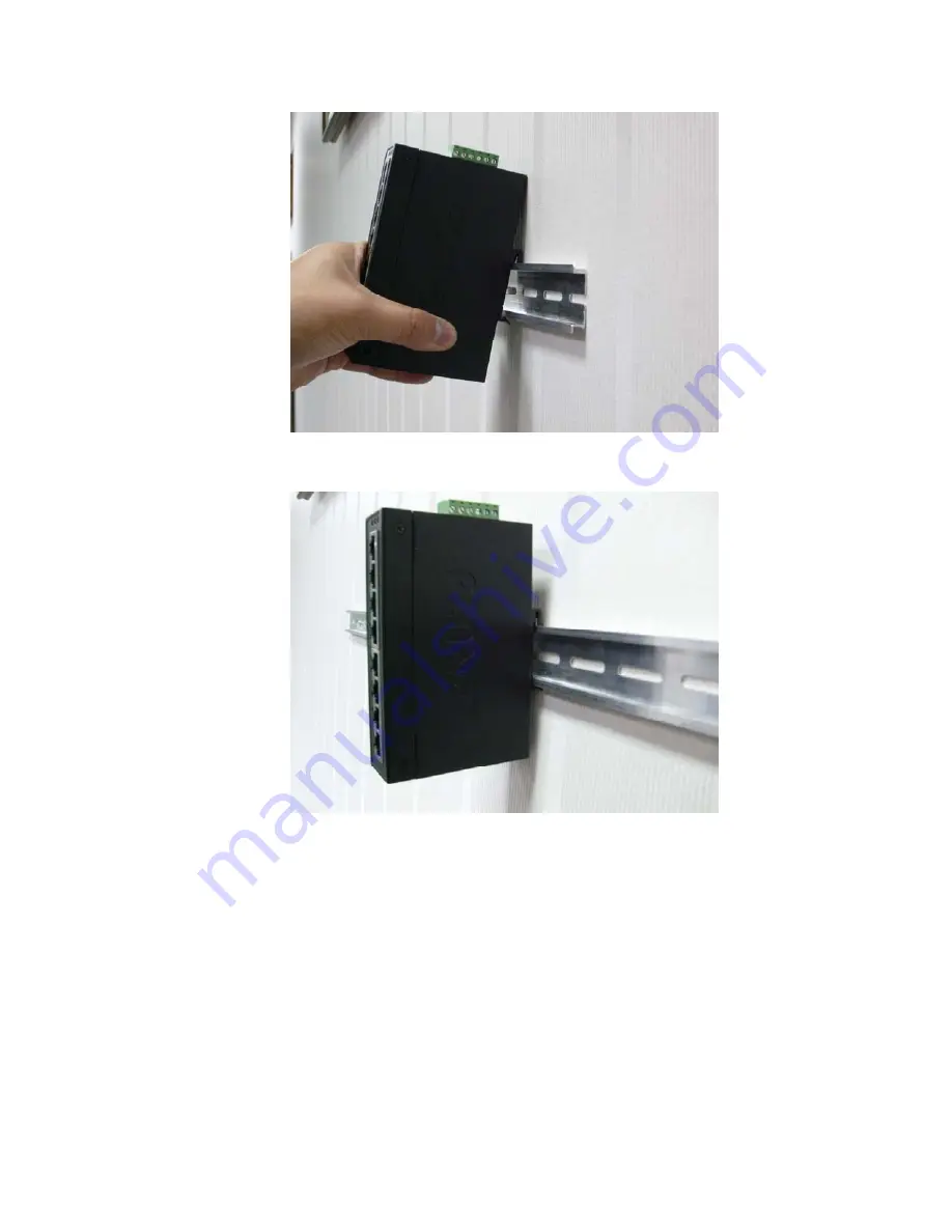
3.  Check that the DIN-Rail is tightly secured on the track. 


4.  Please refer to following procedures to remove the Industrial Gigabit Ethernet 

Switch from the track. 

5.  Lightly press the button of DIN-Rail for remove it from the track. 

GE-DSG-8 DSGH-5 and 8 Ethernet Switch User Manual 

11 

Summary of Contents for GE-DSG-8 DSGH-5

Page 1: ...GE Security P N 1069175 REV 1 01 ISS 03MAR10 GE DSG 8 DSGH 5 and 8 Ethernet Switch User Manual ...

Page 2: ...ine at www gesecurity com This product is intended to be supplied by a UL Listed Direct Plug In Power Unit marked Class 2 or LPS and output rated 48 VDC 380 mA minimum FCC compliance This equipment has been tested and found to comply with the limits for a Class A digital device pursuant to part 15 of the FCC Rules These limits are designed to provide reasonable protection against harmful interfere...

Page 3: ... Alarm Contact 9 Chapter 3 Application 13 Installation Steps 14 Chapter 4 Switch Operation 15 Address Table 15 Learning 15 Forwarding Filtering Store and Forward Auto negotiation Chapter 5 Troubleshooting 19 Appendix A Network Connection 21 Switch s RJ 45 Pin Assignments 21 RJ 45 Connector pin assignment 22 GE DSG 8 DSGH 5 and 8 Ethernet Switch User Manual i ...

Page 4: ...ii GE DSG 8 DSGH 5 and 8 Ethernet Switch User Manual ...

Page 5: ...ding environments Package Contents Check the contents of your package for following parts Industrial Gigabit Ethernet Switch x 1 User s Manual x 1 DIN Rail Kit x 1 Wall Mount Kit x 1 If any of these are missing or damaged please contact your dealer immediately if possible retain the carton including the original packing material and use them against to repack the product in case there is a need to...

Page 6: ...net Switch Product Features Physical Port 5 Port 10 100 1000Base T RJ 45 with auto MDI MDI X function GE DSGH 5 8 Port 10 100 1000Base T RJ 45 with auto MDI MDI X function GE DSG 8 GE DSGH 8 Layer 2 Features Complies with IEEE 802 3 10Base T IEEE 802 3u 100Base TX IEEE 802 3ab 1000Base T Ethernet standard Supports Auto negotiation and 10 100Mbps half full duplex and 1000Mbps full duplex mode High ...

Page 7: ...N Rail and Wall Mount Design 12 to 48V DC redundant power with polarity reverse protect function and connective removable terminal block for master and slave power 10 to 60 Degree C operating temperature on MC 4TX1FXMM 2km MC 4TX1FXSM 15KM MC 4TX2FX GE DSG 8 DSGH 5 and 8 Ethernet Switch User Manual 3 ...

Page 8: ...essure for half duplex IEEE 802 3x Pause Frame for full duplex Switch fabric 10Gbps 16Gbps 16Gbps Throughput Packet per second 7 44Mpps 64bytes 11 9Mpps 64bytes 11 9Mpps 64bytes Jumbo Frame 9Kbytes Network cables 10 100 1000Base T Cat 3 4 5 5e 6 UTP cable 100meters max EIA TIA 568 100 ohm STP 100meters max Environment Specification Operating Temperature 40 C 75 C 40 C 75 C 10 C 60 C Operating Humi...

Page 9: ...h capacity servers The Industrial Gigabit Ethernet Switch has 8K MAC Address table and offers wire speed packets transfer performance without risk of packet loss The Gigabit ports with 9K jumbo packet support can handle large amounts of data transmission in a secure topology linking to a backbone or high power servers The high data throughput of the device makes it ideal for most Gigabit environme...

Page 10: ... a secure topology linking to a backbone or high power servers The Industrial Gigabit Ethernet Switch also supports Store and Forward forwarding scheme to ensure low latency and high data integrity eliminates unnecessary traffic and relieves congestion on critical network paths With an intelligent address recognition algorithm the Industrial Gigabit Ethernet Switch can recognize up to 8K different...

Page 11: ... to the network at 100Mbps Off indicates that the Switch is successfully connecting to the network at 10 or 100Mbps Switch Upper Panel The upper panel of the Industrial Gigabit Ethernet Switch consists of one terminal block connector within two DC power inputs Figure 2 shows the upper panel of the Industrial Gigabit Ethernet Switch Figure 2 Industrial Gigabit Ethernet Switch Upper Panel Wiring the...

Page 12: ...d output rated 48 VDC 380 mA minimum Figure 3 Power Inputs V1 V1 V2 V2 2 Tighten the wire clamp screws for preventing the wires from loosing Figure 3 Terminal Block 1 2 3 4 5 6 Power 1 Fault Power 2 Note The wire gauge for the terminal block should be in the range between 12 24 AWG 8 GE DSG 8 DSGH 5 and 8 Ethernet Switch User Manual ...

Page 13: ...then forms an open circuit The following illustration shows an application example for wiring the fault alarm contacts Figure 4 Fault Alarm contacts 1 2 3 4 5 6 Insert the wires into the fault alarm contacts Note The wire gauge for the terminal block should be in the range between 12 24 AWG Alarm relay circuit accepts up to 30V max 3A currents Figure 5 Alarm schematic Industrial Switch The cloesd ...

Page 14: ...ch Industrial Media Converter are similar Industrial DIN Rail Mounting The DIN Rail is screwed on the Industrial Gigabit Ethernet Switch when in the factory If you need to replace the wall mount application with DIN Rail application on Industrial Gigabit Ethernet Switch please refer to following figures to screw the DIN Rail on the Industrial Gigabit Ethernet Switch To hang the Industrial Gigabit ...

Page 15: ... tightly secured on the track 4 Please refer to following procedures to remove the Industrial Gigabit Ethernet Switch from the track 5 Lightly press the button of DIN Rail for remove it from the track GE DSG 8 DSGH 5 and 8 Ethernet Switch User Manual 11 ...

Page 16: ...ews to remove the DIN Rail 2 Place the wall mount plate on the rear panel of the Industrial Gigabit Ethernet Switch 3 Use the screws to secure the wall mount plate on the Industrial Gigabit Ethernet Switch 4 Use the hook holes at the corners of the wall mount plate to hang the Industrial Gigabit Ethernet Switch on the wall 5 To remove the wall mount plate reverse the steps above 12 GE DSG 8 DSGH 5...

Page 17: ...Chapter 3 Application In this section we will describe how to install the Industrial Gigabit Ethernet Switch into a typical application environment GE DSG 8 DSGH 5 and 8 Ethernet Switch User Manual 13 ...

Page 18: ... The power LED on the Industrial Gigabit Ethernet Switch will light up Please refer to the LED Indicators section for meaning of LED lights 5 Prepare the twisted pair straight through Category 5 cable for Ethernet connection 6 Insert one side of Category 5 cables into the Industrial Gigabit Ethernet Switch Ethernet port RJ 45 port and another side of category 5 cables to the network devices Ethern...

Page 19: ...either forwarding or filtering for future packets Forwarding Filtering When one packet comes from some port of the Industrial Fast Ethernet Switch it will also check the destination address besides the source address The Industrial Fast Ethernet Switch will lookup the address table for the destination address If not found this packet will be forwarded to all the other ports except the port from wh...

Page 20: ...itch can be easily configured in any Ethernet network environment to significantly boost bandwidth using conventional cabling and adapters Due to the learning function of the Industrial Fast Ethernet Switch the source address and corresponding port number of each incoming and outgoing packet are stored in a routing table This information is subsequently used to filter packets whose destination add...

Page 21: ...Chapter 4 Installation GE DSG 8 DSGH 5 and 8 Ethernet Switch User Manual 17 ...

Page 22: ... the partner is set to half duplex then the performance will be poor Per port LED is lit but the traffic is irregular Solution Check that the attached device is not set to dedicate full duplex Some devices use a physical or software switch to change duplex modes Auto negotiation may not recognize this type of full duplex setting Why the Industrial Gigabit Ethernet Switch doesn t connect to the net...

Page 23: ...on Check per port LED on the Industrial Gigabit Ethernet Switch Try another port on the Industrial Gigabit Ethernet Switch Make sure the cable is installed properly Make sure the cable is the right type Turn off the power After a while turn on power again 20 GE DSG 8 DSGH 5 and 8 Ethernet Switch User Manual ...

Page 24: ...witch s RJ 45 Pin Assignments 1000Mbps 1000Base T MDI MDI X Contact 1 BI_DA BI_DB 2 BI_DA BI_DB 3 BI_DB BI_DA 4 BI_DC BI_DD 5 BI_DC BI_DD 6 BI_DB BI_DA 7 BI_DD BI_DC 8 BI_DD BI_DC GE DSG 8 DSGH 5 and 8 Ethernet Switch User Manual 21 ...

Page 25: ...eive 3 Rx receive Tx transmit 4 5 Not used 6 Rx receive Tx transmit 7 8 Not used RJ 45 Connector pin assignment 1 2 3 4 5 6 7 8 8 7 6 5 4 3 2 1 The standard RJ 45 receptacle connector There are 8 wires on a standard UTP STP cable and each wire is color coded The following shows the pin allocation and color of straight cable and crossover cable connection 22 GE DSG 8 DSGH 5 and 8 Ethernet Switch Us...

Page 26: ...Network Connection Please make sure your connected cables are with same pin assignment and color as above picture before deploying the cables into your network GE DSG 8 DSGH 5 and 8 Ethernet Switch User Manual 23 ...

Reviews: