7
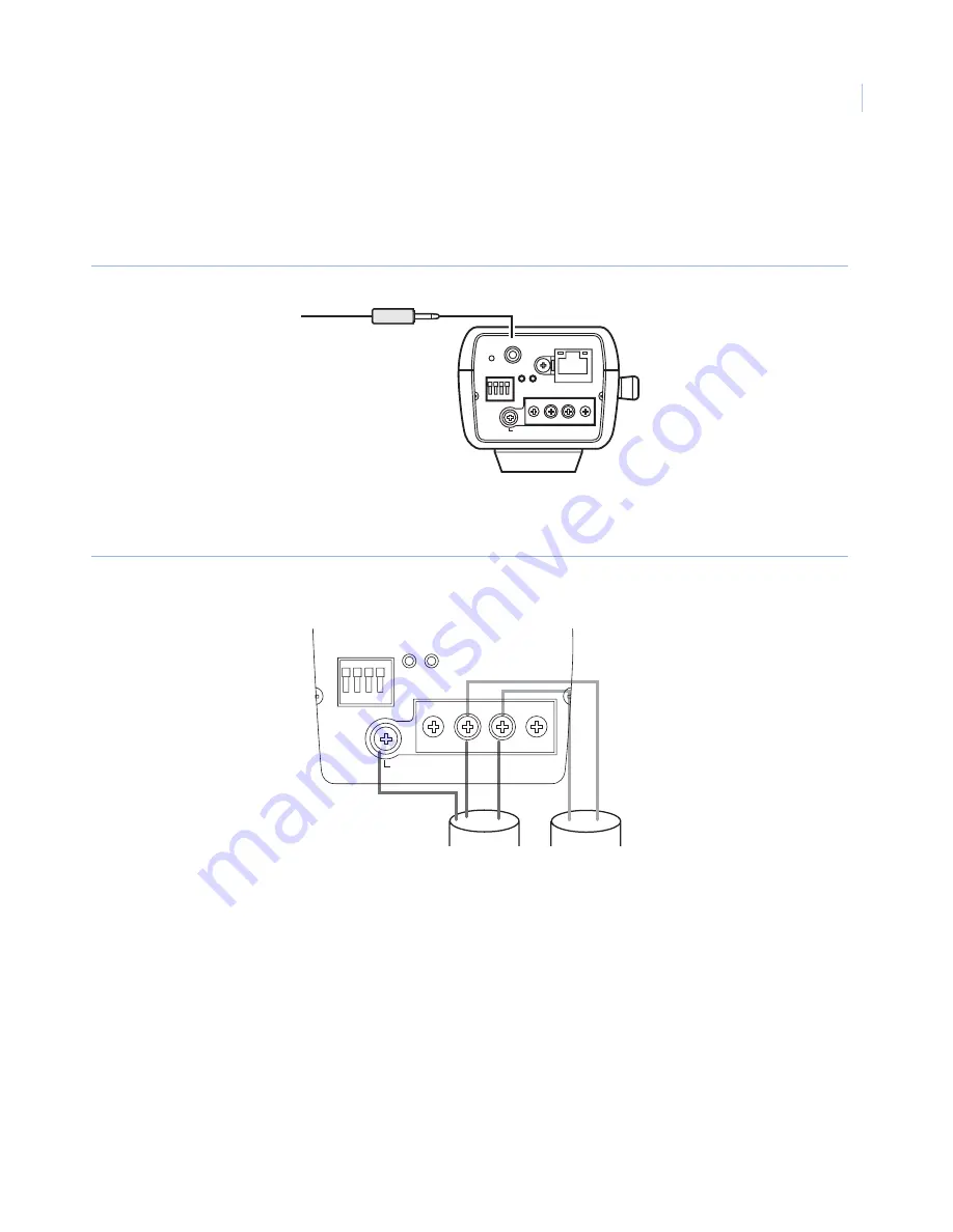
2. Connect the 0.14 in. (3.5 mm) diameter monaural miniplug to the monitor-out connector on the back of
the camera (
Figure 6
). Use the monitor-out connector only to check the angular field-of-view and
focus adjustment on the video monitor when you install the camera, or for servicing. Do not use it for
recording or monitoring.
Figure 6. Video monitor connection
3. Connect the power cable, using one of the following:
•
24 VAC/12 VDC power supply (
Figure 7
).
Figure 7. AC and DC power connections
•
Connect a LAN cable (CAT5 or better) between a PoE (power over Ethernet) device and the
network connector of the camera.
Note:
Using a PoE device is optional if you are using a 24 VAC or 12 VDC power supply.
Use all four pairs (eight pins) of the LAN cable, with a maximum length of 328 ft. (100 m).
Verify the PoE device in use is compliant with IEEE802.3af standard. If you connect the 24 VAC/12
VDC power supply and the PoE device, the PoE is used for the power supply.
If the LAN cable is disconnected when using PoE, wait at least two seconds before reconnecting to
ensure power is re-supplied from the PoE device.
INITIAL SET
GND
POWER
10BASE-T/
100BASE-TX
SD
CARD
MONITOR OUT
EXT I/O
1 2 3 4
LINK
ACT
AC 24V IN : 1L – 2N
DC 12V IN :
!
–
@
Connect to the
video monitor
GND
POWER
SD
CARD
EXT I/O
1 2 3 4
A C 2 4 V I N : 1 L – 2 N
D C 1 2 V I N :
!
–
@
GND wire
24 VAC
12 VDC
_
+


