8. HARDWARE DESCRIPTION
8-2
DTP-B Digital Transformer Protection
GEK-106243E
8.1.3 INTERNAL CONSTRUCTION
Internally, the DTP units consist of the following 4 units high drawout modules:
•
1 power supply module.
•
1 or 2 magnetic modules, depending on the number of windings (analog inputs).
•
1 protection CPU module.
•
1 communications CPU module
•
1 digital inputs & outputs mixed module.
•
1 Sample & Hold Module.
Each of these modules has a DIN type front connector for the connection to the internal communication bus. Also,
in the case of having connections to the outside (inputs, outputs, and power supply modules), the male part of the
terminal block is incorporated. The female part of the connector is located on the rear plate of the case. All these
boards are inserted in the box, perpendicularly to the rear plate.
Besides all these modules, there are some other boards mounted in parallel to the front of the box. These boards
are:
Internal Bus board.
This is a PCB that performs the connection between the digital inputs and the power supply through its front DIN
connectors.
Front Display Board
It is a PCB that includes the LCD display for the protection management, and the configurable LED indicators.
Additionally, the board includes the front communications connector, and the bicolour LED indicator of the unit
status.
The front module is mechanically and solidly connected to the keypad board; the electrical connection is done
through a flexible flat cable of 12 pins.
The subgroup formed by these two front boards is connected to the rest of the unit through another flexible flat
cable of 40 pins, connected to the front of the communications CPU
Front Keypad Board
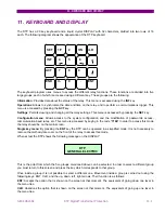
It is a PCB that is solidly joined to the front board of the display, as mentioned before, and supports the keypad for
the protection operation (20-key alpha-numerical keypad controlling the alphanumerical display). The board also
includes a transparent window for the display and for the control board, where the unit identification (model
number and serial number) and its more relevant technical characteristics are included.
The group formed by both front boards is mechanically and electrically joined to the box by means of 4 screws
placed at the bottom and top of the front. In order to access the internal electronic modules of the relay, the
following steps must be followed (once the relay has been disconnected).
1. Remove the plastic cover.
2. Slack the fixed front screws until they are loose and fixed only by their fastening sleeve.
3. Let the front part fall steadily until the flat cable, that is connected to the communications port, is accessible,
and disconnect it from this board.
4. Remove the front module.
Summary of Contents for DTP-B
Page 23: ...3 OPERATING PRINCIPLES 3 6 DTP B Digital Transformer Protection GEK 106243E ...
Page 53: ...10 INSTALLATION AND MAINTENANCE 10 2 DTP B Digital Transformer Protection GEK 106243E ...
Page 68: ...12 FIGURES GEK 106243E DTP Digital Transformer Protection 12 3 Figure 3 RS 232 Connection ...
Page 69: ...12 FIGURES 12 4 DTP B Digital Transformer Protection GEK 106243E Figure 4 Dimensions Diagram ...
Page 70: ...12 FIGURES GEK 106243E DTP Digital Transformer Protection 12 5 Figure 5 Front View ...


