95/TX Operation & Maintenance Manual, Revision 1.0
Page 11
4
INSTALLATION
CHOOSING A LOCATION
The most important role of an Alarm Station is to provide real-time
warning of hazardous conditions that may be present in the vicinity.
As a result, it is
important to install the 95/TX such that the strobe
and/or warning horn provide maximum coverage for the warning area.
At the same time, consideration must be given to the following
conditions: 1) ability to receive gas data packets from all GASMAX/TX
wireless gas detectors; 2) access to a continuous source of AC or DC
power, and 3) maintaining a minimum distance between the antenna
and closest metallic object,
or any object that creates RF interference
such as high voltage power lines or large sodium or mercury vapor
lamps.
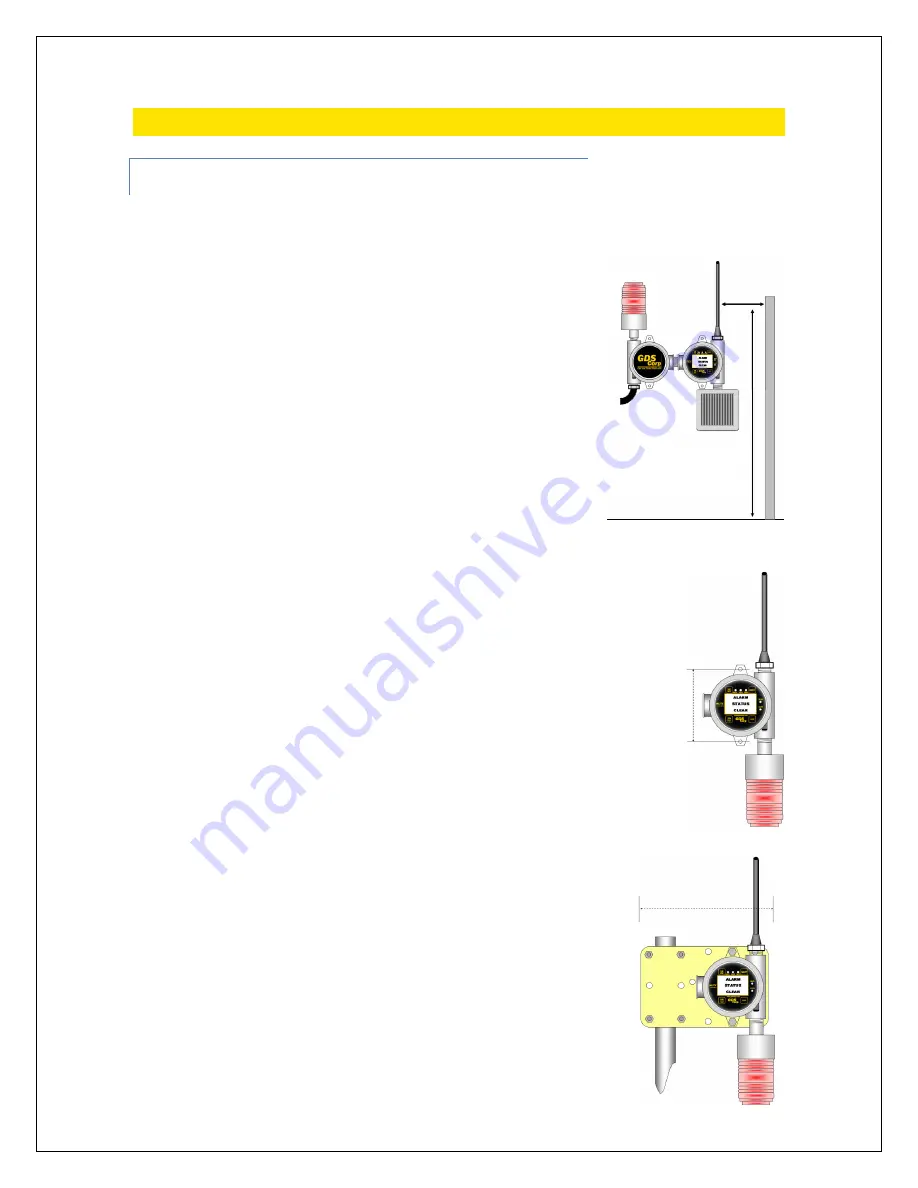
The minimum spacing distance is determined by the RF
frequency chosen and is shown below.
MOUNTING THE 95/TX (Single Enclosure)
The 95/TX standard enclosure is a single cast aluminum explosion-proof
(NEMA 7) enclosure that has two 0.27” diameter mounting holes spaced
5.0” apart. If a local strobe is attached, the strobe body extends 0.5”
behind the plane of the enclosure. If the 95/TX is to be mounted on a flat
plate, then spacers must be installed between the enclosure mounting
holes and the plate to allow for clearance between the strobe and
backplate. Furthermore, if the 95/TX is plate-mounted, the plate should
be designed such that the antenna extends
above
the plate into free
space. Power to the unit should be brought through the left-hand side
¾” NPT threaded opening using an appropriate fitting (not provided).
For pole mount applications, GDS Corp offers a pole mounting kit
(P/N 20-0165) that contains a pre-drilled plate, stainless steel mounting
bolts and two stainless steel U-bolt assemblies. The pole mounting kit
supports poles up to 2.0” in diameter.
Distance from antenna to
nearest metallic surface:
900 MHz => 24” Minimum
2.4 GHz => 6” Minimum
Distance above ground:
6’ / 2m recommended
5.0”
9.5”


