background image

PAGE 6

PAGE 7

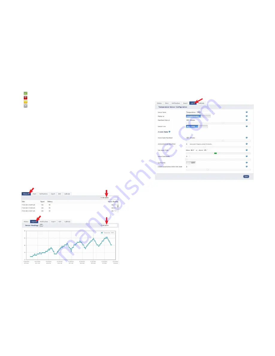
To the left side of each sensor row is an indicator to help you understand the current 
status of the sensor. 

Sensor is checking in and within user defined safe parameters.
Sensor has met or exceeded a user defined threshold or triggered event.
Sensor has not checked in (inactivity alert sent).
No sensor readings will be recorded (Inactive)

Sensor Details View

Clicking on a sensor row on the “Overview” page expands the row to include a detailed 
sensor view for the selected sensor.

Select a tab to change between:

History            - Displays a history of the selected sensor’s data. 
Chart 

         - Displays a graphical view of the selected sensor’s data. 

Notifications    - Allows you to manage notifications for the sensor. 
Export           - Allows you to archive data by exporting as a .csv file.
Edit 

         - Allows you to manage sensor settings.

Calibrate         - Available on certain sensor types to provide more accurate data.

Note: The data shown on the chart, notification, history and export tabs is based on the date 
range indicated on the upper right side of the sensor detail information. To change the date 
range, click inside the date box.

2. History and Chart Views.

Clicking on the “History” or “Chart” tabs within the sensor detail panel allows you to view 
the sensor’s data history as time stamped data or in a graphical chart format.


Note: To change the date range of the viewable information, click on 


the date range box at the top right of the sensor detail panel.

3. Configuring Sensor Settings

To edit a sensors operation settings, click on the sensor overview row to display the details 
view. Click on the “Edit” tab to access the sensor configuration panel.  

The sensor edit panel allows you to set the primary configurations for the sensor. Mousing 
over the question mark icon by each setting will provide an explanation of that setting.  When 
you have finished making changes, press the “Save” button at the  
bottom of this section.   

Note: Be sure to click the “Save” button anytime you make a change to any of the sensor parameters.
All changes made to the sensor settings will be downloaded to the sensor on the next sensor heartbeat 
(check-in).  Once a change has been made and “Saved,” you will not be able to edit that sensor’s configu-
rations again until the sensor has downloaded the new setting. 

Summary of Contents for G-HUB

Page 1: ...the connection is snug but do not overtighten Plug an Ethernet cable with internet connectivity into the gateway Plug the power supply into a power outlet then connect to the gateway Once all three l...

Page 2: ...2 Indicates the Ethernet has internet connectivity and can reach the online moni toring system A green light indicates ready and working a red light indicates there is a problem A flashing green ligh...

Page 3: ...e immediate response from the sensor power cycle the sensor by removing then re inserting the battery Notes If the sensor status indicator does not change reset the sensor by removing the battery Wait...

Page 4: ...sensor detail information To change the date range click inside the date box 2 History and Chart Views Clicking on the History or Chart tabs within the sensor detail panel allows you to view the sens...

Page 5: ...ws the user to set notifications based on advanced rules such as comparing past data points with the current one to determine if a notification should be sent Existing Notifications Use notifications...

Page 6: ...n your network you will also see a Devices to Notify tab This will allow the notification to interact with these types of devices Select a device from the list on the left and click the arrow button t...

Page 7: ...tive and Save The default port is 3500 but can be edited PAGE 12 PAGE 13 5 Advanced Settings and Interfacing with the G HUB Ethernet Gateway Through iG HUB 1 Ethernet Gateway Edit Screen When you log...

Page 8: ...erface Active and Save The MODBUS TCP Interface will store all data values in 16 bit registers The registers and their data fields are mapped below Field Description Register Data Address GATEWAY Gate...

Page 9: ...Device Count WNetSection Wireless Network Seciont WD Entry Wireless Device Entry Index Index Number Serial Wireless Device Serial ID Type Device Type eg temp water motion sensor etc Age Number of sec...

Page 10: ...the PC firewall does not prohibit an inbound connection Plug power cable into the Ethernet gateway Plug in the power cable While the device is booting press and hold the Reset Button on the back of th...

Page 11: ...ipt of the product G HUB reserves the right to repair or replace products at its own and complete discretion Customer must obtain from G HUB a Return Material Authorization Number RMA prior to returni...

Page 12: ...her antenna or transmitter PAGE 22 PAGE 23 Canada IC English Under Industry Canada regulations this radio transmitter may only operate using an antenna of a type and maximum or lesser gain approved fo...

Page 13: ...ons on how to use your G HUB Wireless Sensors or the iG HUB Online System please visit us on the web at http www G HUB com support Global Design Corporation Inc 67 East Park Place Suite 750 Morristown...

Reviews: