


3.2 PARALLEL TRANSMISSION
3.2.1 Connecting to the Parallel Port (Centronics)
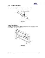
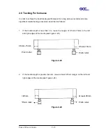
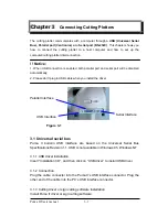
1. Connect a parallel cable to the cutting plotter and the host computer (Figure3-1).
2. Set up the output port
LPT1
or
LPT2
from your software package
3. Send the data to your cutting plotter directly. Or, use DOS commands like
TYPE
or
to output data.
3.3 SERIAL TRANSMISSION
3.3.1 Connecting to the Serial Port (RS-232C)
1. For PC users, please connect the RS-232C cable to the serial connector of the
assigned serial port (COM1 or COM2) of your host computer.
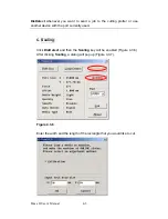
2. Set up the communication parameters (Baud Rate, Data Bits/Parity and Stop Bits)
to match the setting on the computer.
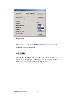
3.3.2 Transmitting the Data to Plotter
There are two options to transmit the data from the computer to the cutting plotter:
Option 1
With proper interface settings, the data can be transmitted from your application
software package to the cutting plotters directly.
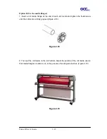
Option 2
Most cutting software packages are able to emulate
HP-GL
or
HP-GL/2
commands,
therefore, Use DOS commands like
TYPE
or
to output your file. As long as the
file is
HP-GL
or
HP-GL/2
format, the cutting plotter can output the data precisely.
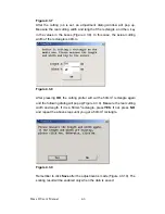
For example, a file with
PLT
extension generated by
SignPal software, FlexiSign or
SignLab
can be transmitted directly to the plotter at the DOS prompt, and then be cut
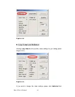
out. Before outputting at the DOS prompt, set up a transmission protocol between
your cutting plotter and computer by a DOS command, MODE. Make sure that your
PC has the same communication protocol as the cutter. For example:
MODE COM2: 9600,N, 8,1,P
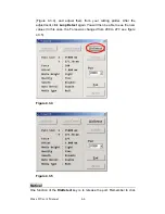
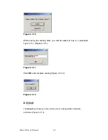
Then
, use
TYPE
command to output via
COM2
if
COM2
is the assigned output port.
Puma II Users manual 3-2
Summary of Contents for PII-132S
Page 1: ...Puma II users manual...