Version : 9.0
39
4.1.6 Main board Connection or Replacement
Main board connection or replacement must follow the following steps to be sure that no damage
comes to either service personnel or the components:
Note:
To ensure absolute safety for service personnel and components, please follow the safety instruction at
the beginning of this manual, before installing or replacing any current carrying components
1. Unplug all of the jumpers and connectors attached to all of board components.
(Note: Please refer to the Jaguar Wiring Diagram for more detail on jumper and connector attachment)
4.1.7 Replacement
of Fuses
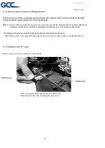
The Fuse pops out for easy replacement as follows:
Holding clip
Holding clip
With your fingers apply equal pressure to both of the
holding clips on the Fuse housing, and push it out.
Summary of Contents for J5 Series
Page 1: ...Version 9 0 1 J5 J5 LX Series Maintenance Manual...
Page 5: ...Version 9 0 5 2 1 Main Unit Assembly...
Page 8: ...Version 9 0 8 2 2 Left End Assembly...
Page 10: ...Version 9 0 10 2 3 Right End Assembly 290106350G Flat cable 9 pin to 8 pin PCB Assembly...
Page 12: ...Version 9 0 12 2 4 Motor Bracket and Belt Assembly...
Page 14: ...Version 9 0 14 2 5 Carriage Assembly...
Page 16: ...Version 9 0 16 2 6 LX Carriage Assembly AAS...
Page 19: ...Version 9 0 19 2 7 Pinch Roller Assembly...
Page 21: ...Version 9 0 21 2 8 Main Beam Assembly...
Page 23: ...Version 9 0 23 2 9 Drum Assembly...
Page 25: ...Version 9 0 25 Chapter 3 Circuit System 3 1 System Diagram...


