Version : 9.0
28
Chpater 4 Maintenance
This chapter deals with
component
replacement and
maintenance
of the J5 Cutting Plotter.
It
gives detailed
step-by-step instruction
on how to replace or adjust the
components
of this
machine.
4.1 Components Replacement and Belt Tension Adjustment
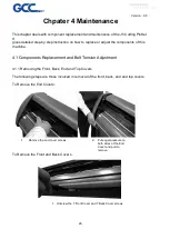
4.1.1 Removing the Front, Back, End and Top Covers
The following steps are those involved in removal of the front, back, end and top covers.
To Remove the End Covers:
1.
Remove the end cover screws.
2. Put equal pressure on
both sides of the End
Cover and pull to
remove.
To Remove the Front and Back Covers :
1. Unscrew the 7 Front Cover and 7 Back Cover screws
Summary of Contents for J5 Series
Page 1: ...Version 9 0 1 J5 J5 LX Series Maintenance Manual...
Page 5: ...Version 9 0 5 2 1 Main Unit Assembly...
Page 8: ...Version 9 0 8 2 2 Left End Assembly...
Page 10: ...Version 9 0 10 2 3 Right End Assembly 290106350G Flat cable 9 pin to 8 pin PCB Assembly...
Page 12: ...Version 9 0 12 2 4 Motor Bracket and Belt Assembly...
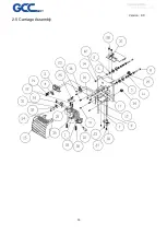
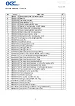
Page 14: ...Version 9 0 14 2 5 Carriage Assembly...
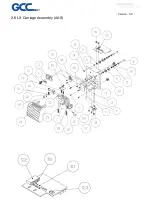
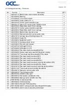
Page 16: ...Version 9 0 16 2 6 LX Carriage Assembly AAS...
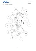
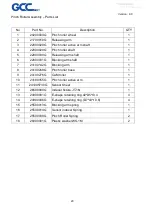
Page 19: ...Version 9 0 19 2 7 Pinch Roller Assembly...
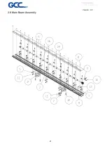
Page 21: ...Version 9 0 21 2 8 Main Beam Assembly...
Page 23: ...Version 9 0 23 2 9 Drum Assembly...
Page 25: ...Version 9 0 25 Chapter 3 Circuit System 3 1 System Diagram...

