background image

Safety

F-36 PRO Laminator Operation Manual

1-6

© GBC Pro-Tech 1999 January

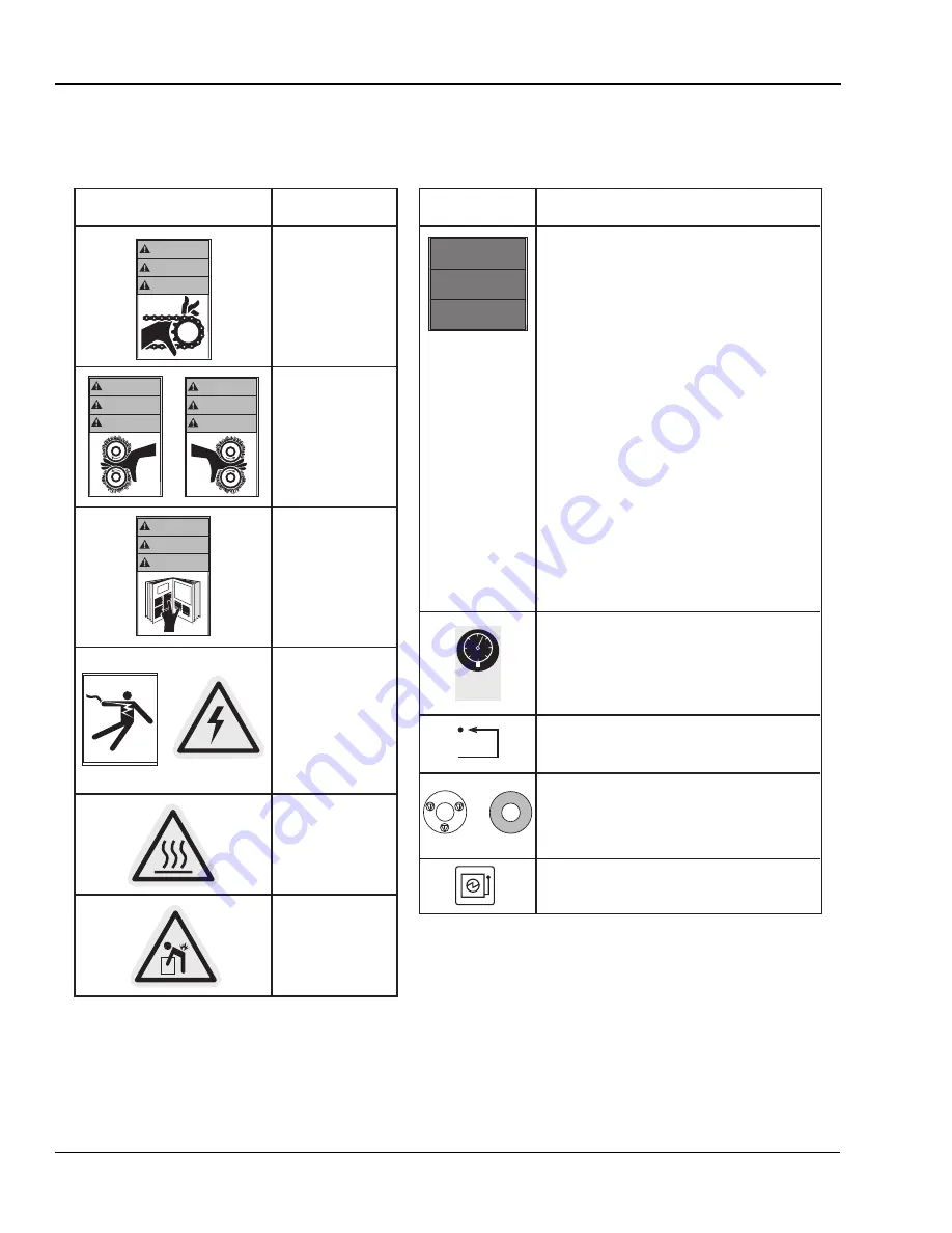
The following are typical safety hazard decals used on GBC Pro-Tech machines, with a brief description (“Mean-
ing” column) of each decal.

WARNING!

Moving parts can
crush and cut.

Do not operate with
guard or door open.

WARNING!

Crush and burn
hazard. Stay clear of
moving rollers. Stop
machine and raise roll
before cleaning.

WARNING!

Carefully read
Operator's Manual
before handling this
machine. Observe
instructions and safety
rules when operating.

WARNING!

HAZARDOUS
VOLTAGE.

To be serviced only by
trained and authorized
personnel.

Lockout power before
servicing.

Reset.

CAUTION!

Surface is hot.

A burn hazard exists.

WARNING!

1.

Read and understand the Operation Manual and
all safety labels before operating this machine.

2.

Only a trained person is to be permitted to operate
this machine. Training should include instruction
in operation under normal conditions and
emergency situations.

3.

This machine is to be serviced only by trained and
authorized personnel. Follow lockout procedures
before servicing.

4.

Never reach into the machine for any reason unless
the machine is at a COMPLETE STOP.

5.

Never leave the machine stopped in such a manner
that another worker can start the machine while
you are working on or within the machine.

6.

Never change or defeat the function of electrical
interlocks or other machine "shutdown" switches.

7.

Before starting this machine, check that:
-  All persons are clear of the machine.
-  No maintenance work is being performed on

the machine.

-  All guards are in place.
-  All parent rolls are well chucked in the unwind

stands.

-  The machine is free of paper scraps, wraps and

jams.

8.

There is a potential hazard of entanglement in this
machine caused by items such as long hair, loose
clothing, and jewelry. Make sure your clothing and
hair fit closely to your body and that all jewelry,
rings and watches are removed.

Decal

Meaning

Decal

Meaning

or

WARNING

ACHTUNG

MISE EN GARDE

WARNING

ACHTUNG

MISE EN GARDE

or

 100 PSI

 700 KPa

©1997 HCS, Inc. 800-748-0241 No. 6101-52BVPK

CAUTION!

Rolls are heavy.
Use proper lifting
techniques to prevent
injury.

CAUTION!

Air pressure must be less than 100 PSI (700 kPa) to
avoid damaging the machine.

or

NO

T

A

U

S

E

M

E

R

G

EN

CY

STOP

A

R

R

E

T

D

'U

R

G

EN

CE

WARNING!

EMERGENCY STOP BUTTON

Press this button to stop the machine cycle, remove
electric power, and separate (open) rolls to eliminate a
pinch point (on some machines).

Electric power disconnect and lock out location.

WARNING

ACHTUNG

MISE EN GARDE

WARNING

ACHTUNG

MISE EN GARDE

SAFETY
INSTRUCTIONS

SICHERHEITS-
RICHTLINIEN

CONSIGNES DE
SÉCURITÉ

©1994 Hazard Communication Systems, Inc. 800-748-0241

Summary of Contents for F-36

Page 1: ...ARRET D U R G E N C E NOT AUS E M E R G E N CY STOP ARRET D U R G E N C E 18 16 48 12 10 8 6 4 2 0 50 75 100 125 150 175 200 225 250 275 300 OUT HI LO PROT ECH F 001 133 50 75 100 125 150 175 200 225...

Page 2: ...s publication and to the products described in it without notice All specifications and information concerning products are subject to change without notice Reference in this publication to informatio...

Page 3: ...erials 3 4 Films Excluding Vinyl Transfer and Overlamination 3 4 Positioning the Film 3 4 Heating 3 4 Cooling 3 5 Paper Tips 3 5 Process Control Charts 3 5 Mounting and Laminating One Pass 3 5 Setup a...

Page 4: ...nuary Machine Shutdown 3 8 Procedure 3 8 Thermocouple Positioning and Cleaning 4 1 Adjusting the Nip 4 5 Chain Tensioning 4 6 Lubrication 4 7 Contacting Technical Support 4 7 Output Troubleshooting Gu...

Page 5: ...urn if the rolls are touched during set up operation or ser vicing An important feature of the laminator is the guard that stops the machine when opened However this system is overridden if you use th...

Page 6: ...hen operating the laminator with the footswitch The guard is overridden and your fingers can get caught in the nip You can be crushed or burned NOT AUS EM E R G E N C Y S T O P AR R E T D U R G E N CE...

Page 7: ...upper or lower roll remove it IMMEDIATELY using 80 isopropyl alcohol It can harden within an hour and ruin the roll The operating environment must be free of dust flammable liquids and vapors You can...

Page 8: ...e The three prong plug fits only into a grounding type power outlet If you are unable to insert the plug into the existing outlet contact a qualified electrician to replace the obsolete outlet Do not...

Page 9: ...LVM 240C WARNING ACHTUNG MI SE EN GA RD E 199 4 Haza rd Com muni catio n Syste ms Inc 800 7 48 02 41 18 16 48 12 10 8 6 4 2 0 50 75 100 125 150 175 200 225 250 275 300 OUT HI LO PRO TECH F 001 13 3 50...

Page 10: ...art the machine while you are working on or within the machine 6 Never change or defeat the function of electrical interlocks or other machine shutdown switches 7 Before starting this machine check th...

Page 11: ...air However the laminator must not be located where there is air blowing directly on it Major fluctuations in temperature and humidity are to be avoided WARNING CAUTION Is there an appropriate power s...

Page 12: ...tion F 36 PRO Laminator Operation Manual 2 2 GBC Pro Tech 1999 January Figure 2 1 Laminator Space Requirements 4 6 1 1m 2 2 7m 10 3m 10 3m 3 1m 73 1 8m Floor Trimmer 3 x 6 1m x 2m Table Recommended cl...

Page 13: ...screwdriver 7 8 open end wrench or adjustable wrench If the laminator is in a cardboard box 1 Remove the securing screws around the bottom of the box using the Phillips head screwdriver as shown in F...

Page 14: ...ock they are pre treated with a VCI protective film to provide total cor rosion protection This protective film is wrapped around the machine and completely sealed In addition moisture absorbing silic...

Page 15: ...requires lifting the laminator Do not allow the top to fall into the crate It can damage the laminator Do not put packing screws on the floor They can cause problems when trying to roll the machine in...

Page 16: ...al position check each of the following items Tools required 1 8 hex wrench Adjustable wrench Setup Procedure 1 Inspect the laminator for any obvious shipping damage 2 Remove the drive and control sid...

Page 17: ...phase 240 400 VAC with 20A per phase See Figure 2 6 for power cord connection options 8 Replace both cabinet covers Figure 2 6 Power Cord Connection ALWAYS CHECK THE SENSORS PRIOR TO OPERATION The se...

Page 18: ...op Replace the guard so that the switch is engaged The laminator should resume operation WARNING Is the motor functioning Test the motor at various speeds ranging from 0 18 At 0 the rolls should stop...

Page 19: ...hed the rolls resume turning However this system is overridden if you use the footswitch WARNING The F 36 PRO Laminator has a steel cabinet that is bolted closed to isolate the electrical and drive sy...

Page 20: ...e lower roll and the set point for the desired temperature Figure 3 3 Heater Controller 9 AUTO STOP Turns the drive system on or off 10 MOTION CONTROL FORWARD REVERSE Controls the direction of the dri...

Page 21: ...he process of loading and aligning film is the same for both the top and the bottom unwinds There are two important points to remember when loading film 1 The adhesive side of the film must be oriente...

Page 22: ...over to support the laminating film s end 4 Secure the support arm Use the following instructions when heating one or both of the laminating rolls The procedure is the same for the top and bottom heat...

Page 23: ...n a very accurate and repeatable manner The charts provide a way to set up each time every time for repeatable performance by assuring that all controls are set to optimum The process control charts s...

Page 24: ...e board and image into the nip Be sure to keep it perpen dicular to the laminating rolls and maintain paper tension throughout the process Note Some images will release toner or ink to the upper lam i...

Page 25: ...l Drape the film only about halfway down the upper main roll 3 Pull the mount adhesive straight up from the lower unwind position being careful not to stick the film to the machine Tack it to the hot...

Page 26: ...ard into the nip and lower the upper main roll Press the footswitch Once the leader board is through the nip release the foot switch Lower the roll 1 2 a turn past the initial contact of the upper lam...

Page 27: ...___________ __________________________________________________________________________________________ __________________________________________________________________________________________ MATERI...

Page 28: ..._______________________________ ___________________________________________________________________________________________ MATERIALS Upper Media 3 mil gloss Image Media Bond Paper Lower Media N A Mou...

Page 29: ...__________________________________ __________________________________________________________________________________________ MATERIALS Upper Media N A Image Media Bond Paper Lower Media N A Mounting...

Page 30: ...________________________________________________ ___________________________________________________________________________________________ MATERIALS Upper Media Pro Gloss Image Media Bond Paper Lowe...

Page 31: ..._______________________________________________________ __________________________________________________________________________________________ MATERIALS Upper Media N A Image Media N A Lower Media...

Page 32: ...______________________________________________________________ ___________________________________________________________________________________________ MATERIALS Upper Media 3 mil Gloss Image Media...

Page 33: ...___________________________ __________________________________________________________________________________________ MATERIALS Upper Media N A Image Media N A Lower Media N A Mounting Substrate Foam...

Page 34: ..._____________________________________ ___________________________________________________________________________________________ MATERIALS Upper Media 3 mil Gloss Image Media Bond Paper Lower Media 3...

Page 35: ...in Figure 4 3 2 Remove the two screws securing the thermocouple to the laminator using the 1 8 hex wrench and take the thermocouple out 3 Inspect the thermocouple If there is any adhesive or dirt on...

Page 36: ...n Figure 4 2 Figure 4 2 Correct Thermocouple Contact CAUTION 5 Replace the thermocouple and tighten the screws 6 Repeat the procedure for the other thermocouple Firmly hold the thermocouple where the...

Page 37: ...994 HCS Inc 800 748 0241 Reorde r No 1033 PT Cr us h an d bu rn ha zard Stay cle ar of mo vin g rol ler s Stop ma ch ine an d rai se rol l be for e cle an ing WARNING ACHTU NG MI SE EN GA RD E NOT AUS...

Page 38: ...ls by running an adhesive coated board through the lam inator Be sure to set the nip for the thickness of the board used 5 Allow the laminator to cool Exercise extreme caution while cleaning the lamin...

Page 39: ...you are performing this pro cedure 2 Remove the drive and control side cabinet covers with the 1 8 hex wrench by removing the six screws holding each cover in place 3 Using the handwheel lower the up...

Page 40: ...required 1 8 hex wrench 3 16 hex wrench Screwdriver To adjust the chain tension 1 Unplug the laminator and make sure it won t be plugged back in while you are performing this pro cedure 2 Remove the...

Page 41: ...s and reconnect power to the laminator For machine parts and technical service in North America please call 1 800 790 7787 Please provide serial number when calling for service In Europe please call 4...

Page 42: ...operational settings for materials being used Problem Waves on only one side of the output Hints Check nip settings Check for even paper tension Other Common Problems Problem Blistering in the image...

Page 43: ...arranty specifically does not cover damage to the laminating rollers caused by knives razor blades other sharp objects failure caused by adhesives or improper use of the machine Warranty repair or rep...

Page 44: ...Warranty F 36 PRO Laminator Operation Manual 5 2 GBC Pro Tech 1999 January Blank page...

Page 45: ...witch Encapsulating Features Pull rolls and cooling fans for uniform flat cooling Safety Features Mechanical guard on infeed All electrical and moving mechanical parts are located in bolted cabinets R...

Page 46: ...Specifications F 36 PRO Laminator Operation Manual 6 2 GBC Pro Tech 1999 January Blank page...

Page 47: ...Handwheel 2 6 4 5 Heater 2 8 Controller 2 8 Heating 3 4 Infeed table 4 4 Installation requirements 2 1 6 1 Laminate adhesives 3 4 Laminating material 6 1 Laminating opening 6 1 Laminating rolls 6 1 La...

Page 48: ...apsulating 6 1 Laminating material 6 1 Laminating opening 6 1 Laminating rolls 6 1 Laminating speeds 6 1 Weight 6 1 Technical support Call 1 800 236 8843 4 7 Thermocouple 4 1 4 2 4 3 Locations 4 3 the...

Reviews: