GBC 620os
Operation Manual
© 2007 General Binding Corporation
Page 11
FEATURES/ACCESORIES GUIDE
V
Y
X
W
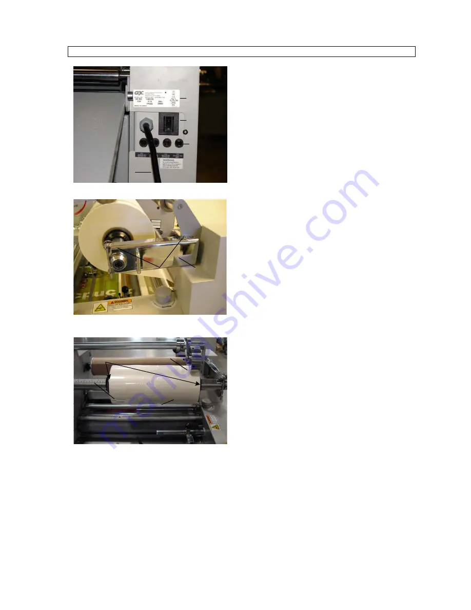
Figure 9
Z
A1
Figure 10
B1
C1
D1
E1
Figure 11
NOMENCLATURE PLATE
(
Fig. 9– Item V)
The
Nomenclature Plate
provides the operator the
necessary Technical information such as Voltage,
Amperage, Wattage, Model Number and Serial Number.
MAIN ON/OFF SWITCH
(
Fig. 9– Item W)
The
Main On/Off Switch
supplies power or removes
power from the machine.
FUSES
(
Fig. 9– Item X)
The
Fuses
protect internal PCB’s and motors.
POWER CORD
(
Fig. 9– Item Y)
The
Power Cord
plugs into the Main Power source or
outlet. See (Machine Specs for plug requirements.)
LOCKING PINS
(
Fig10– Item Z)
The
Locking Pins
secure the
Film Shaft Latch.
FILM SHAFT LATCH
(
Fig. 10– Item A1)
The
Film Shaft Latch
secures the Supply shaft ensuring
that the film is supported and enters the nip accurately.
PRELAMINATING FILM PERFEORATOR WHEEL
(
Fig. 11– Item B1)
The
Prelaminating Film Perforator Wheel
pierces small
holes into the film to ensure controlled snapping or
separating of images.
FILM CORE CHUCKS
(
Fig. 11– Item C1)
The
Film Core Chucks
secure the film onto the
Supply
Shaft.
FILM SUPPLY SHAFT
(
Fig. 11– Item D1)
The
Film Supply Shaft
accepts a 3 inch
Core Chuck
. The
two
Core Chucks
slide onto the
Film Supply Shaft
,
supporting the film being used. The
Film Supply Shaft
has a ruler adhered to the shaft for ease and accuracy when
aligning the film and medias.
TOP FILM IDLER
(
Fig. 11– Item E1)
The
Top Film Idler
guides the film through the nip giving
the film adequate film dwell time.


