CHAPTER 4: Installing Components
40
8
When the processor is oriented correctly and in place, press it firmly into the socket, rotate
the retention lever into place until it clicks.
9
Place the heatsink down onto the processor, then gently tighten the heatsink retaining
screws to secure it into place.
10
Follow the instructions in
“To close the server case:” on page 24
.
Replacing a power supply module
If your server uses the optional hot-swappable, redundant power supplies and one of the two
power supplies fails, the other power supply module supports the server while you replace the
failed module. You do not need to turn off the server or disconnect peripheral devices to replace
a failed power supply module.
To replace a power supply module:
1
If you only have one power supply module, turn off your server.
2
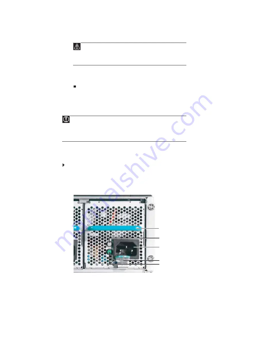
If you have two power supply modules, examine the LED indicators on the back of each
power supply module to identify the failed module. The power supply module has failed
if the orange (right) LED indicator is on.
3
Unplug the power cord from the failed power supply module.
Caution
The heatsink has Thermal Interface Material (TIM) located on the bottom of
it. Use caution when you unpack the heat sink so you do not damage the TIM. If
you are reusing the original heatsink, make sure that the TIM on the bottom of
the heatsink is not damaged. If the TIM is damaged, you should remove the old
TIM, then apply new TIM to the bottom of the heatsink.
Warning
The power supply modules in this server contain no user-serviceable parts. Only a
qualified computer technician should service the power supply modules.
Your server comes with 3-wire AC power cords fitted with the correct plug style for your
region. If this plug does not match the connector on your surge protector, UPS, or wall
outlet, do not attempt to modify the plug in any way. Use a UPS or wall outlet that is
appropriate for the supplied AC power cords.
Power supply fault LED
Power on LED
Power connector
Power supply latch
Power supply handle
Summary of Contents for E-9232T
Page 1: ... E 9232T Server USERGUIDE ...
Page 2: ......
Page 6: ...Contents iv ...
Page 7: ...CHAPTER1 1 Checking Out Your Gateway Server Front Back Interior System board Getting Help ...
Page 12: ...CHAPTER 1 Checking Out Your Gateway Server 6 ...
Page 52: ...CHAPTER 4 Installing Components 46 ...
Page 69: ...APPENDIXA 63 Server Specifications ...
Page 74: ...APPENDIX A Server Specifications 68 ...
Page 75: ...APPENDIXB 69 BIOS Settings ...
Page 84: ...APPENDIX B BIOS Settings 78 ...
Page 85: ...APPENDIXC 79 Legal Information ...
Page 90: ...APPENDIX C Legal Information 84 ...
Page 94: ...88 www gateway com ...
Page 95: ......
Page 96: ...A MAN E 9232T USR GDE R1 9 07 8512069 Back fm Page 8 Wednesday August 29 2007 3 28 PM ...


