background image

 Getting Started     3

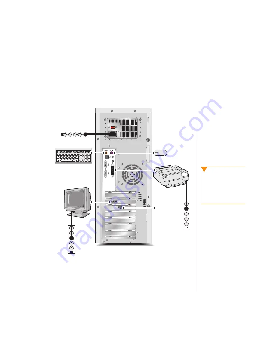
The following figure shows you how to connect basic peripherals to your 
computer. Note that your system may not include all the items shown in the 
figure.

Some connectors on the back of the system are colored to match the plugs 
on peripherals that ship with your system. For more detailed information on 
connecting peripherals, see “Rear Panel” on page 16.

Network

 Caution!

Make sure your computer 
and peripherals are turned 
off and unplugged from the 
power outlet when you 
connect peripherals to the 
system.

Summary of Contents for E-5200

Page 1: ...E 5200 User s Guide MAN SYS US E5200 USR GDE R0 6 98 8502954...

Page 2: ...US E5200 USR GDE R0 5 98 In our effort to use nature s resources efficiently and wisely we print all manuals on recycled papers that meet the minimum requirements established by the Federal EPA in it...

Page 3: ...incidental or consequential damages resulting from any defect or omission in this manual even if advised of the possibility of such damages In the interest of continued product development Gateway 20...

Page 4: ...ting Your System 8 System Features 9 System Features 10 AGP Video 10 BIOS 10 Cache Memory 10 Connectors 10 Drives 11 Expansion Slots 11 Intel 440 BX Chip Set 11 Manageability 12 Memory 12 Networking 1...

Page 5: ...tem 19 Maintaining the Hard Drive 20 Cleaning Your System 21 Cleaning the Mouse 21 Cleaning the Keyboard 21 Cleaning the Monitor Screen 22 Cleaning the Computer and Monitor Cases 22 Appendix 23 Acrony...

Page 6: ...that the keys must be pressed simultaneously Setup Commands to be entered options to select and messages that appear on your monitor are printed in bold User s Guide Names of publications and files a...

Page 7: ...jects of any kind into the system ventilation slots Use the voltage setting for your area The voltage selector switch is set at the factory to the correct voltage This system is equipped with a 3 wire...

Page 8: ...rer Dispose of used batteries according to the manufacturer s instructions Unplug the system from the wall outlet and refer servicing to qualified personnel if The power cord or plug is damaged Liquid...

Page 9: ...vi E 5200 User s Guide...

Page 10: ...Getting Started Contents Assembling Your System 2 Starting Your System 4 Turning Off Your System 7 Resetting Your System 8...

Page 11: ...ed power strip helps protect against AC line spikes Protect your computer from extreme temperature and humidity Do not expose your computer to direct sunlight heater ducts or other heat generating obj...

Page 12: ...the figure Some connectors on the back of the system are colored to match the plugs on peripherals that ship with your system For more detailed information on connecting peripherals see Rear Panel on...

Page 13: ...strip 2 Press the power button on the monitor to turn on the monitor 3 Press the power button on the computer to turn on the computer The power LED light emitting diode on the front panel is lit when...

Page 14: ...ntrast controls on the monitor For more troubleshooting information see the Troubleshooting chapter in the Maintaining and Troubleshooting Your E 5200 System guide Understanding the Power On Self Test...

Page 15: ...e finished entering the information click Next 3 Continue following the instructions and selecting options in the Start up wizard dialog boxes clicking Next to move through the dialog boxes until the...

Page 16: ...hen you see a message saying It is now safe to turn off your computer press your computer s power button to turn off the computer and then turn off the monitor and peripherals To turn off your system...

Page 17: ...sk Manager select the program that is not responding and click End Task 3 If your computer does not respond press the power button on the computer The computer turns off 4 Wait a few seconds and then...

Page 18: ...Chapter 1 System Features Contents System Features 10 Front Panel 14 Rear Panel 16...

Page 19: ...and monitor without using programs on the hard drive The battery in your computer maintains the BIOS settings in CMOS memory even when the computer is turned off You can change the BIOS settings thro...

Page 20: ...FAT16 and NTFS are different methods the operating system uses to locate files on a hard drive NTFS supports large drive sizes but NTFS partitions cannot be viewed with MS DOS Microsoft disk operating...

Page 21: ...r settings are required for the memory size or type because this information is automatically detected by the BIOS For information on installing additional memory see the Installing and Removing Compo...

Page 22: ...cessors in your system should be of the same clock speed For information on removing and installing a processor see the Installing and Removing Components chapter in the Maintaining and Troubleshootin...

Page 23: ...Jack You can connect headphones or powered speakers to the audio out jack CD ROM Drive The high speed CD ROM drive enables you to play data or audio CDs CD ROM drive Power LED CD ROM drive eject butto...

Page 24: ...om 3 5 inch 1 44 MB diskettes Hard Drive LED The hard drive LED is lit when the hard drive is active Power Button Push in the power button once to turn on the computer and push it in again to turn off...

Page 25: ...rs and switches Keyboard Port Plug a PS 2 Personal System 2 compatible keyboard into this port Mouse Port Plug a PS 2 compatible mouse into this port Voltage selector Power connector Keyboard port USB...

Page 26: ...rument digital interface devices into these ports USB Ports USB universal serial bus ports connect external Plug and Play devices that are automatically configured when they are plugged into the syste...

Page 27: ...18 E 5200 User s Guide...

Page 28: ...Maintaining and Cleaning Your System Contents Maintaining the Hard Drive 20 Cleaning Your System 21...

Page 29: ...n the drive Use Check Disk from once a week to once a month depending on how often you use your computer Also use Check Disk whenever you have any hard drive problems 1 Right click Start and then clic...

Page 30: ...adhesive tape to pick up any dust or lint on the surface of the ball and wipe away dirt or lint inside the ball socket You can also blow into the socket to remove dirt and lint If foreign matter is tr...

Page 31: ...aning the Monitor Screen Use a soft cloth and window cleaner to clean the monitor screen Squirt a little cleaner on the cloth never directly on the screen and wipe the screen with the cloth Cleaning t...

Page 32: ...Appendix Contents Acronyms and Abbreviations 24 Terms and Definitions 26...

Page 33: ...amic random access memory ECC Error correcting code FAT File allocation table GB Gigabyte IDE Integrated drive electronics IRQ Interrupt request line LAN Local area network LED Light emitting diode MB...

Page 34: ...Appendix A 25 SCSI Small computer system interface SDRAM Synchronous dynamic random access memory TCP IP Transmission control protocol Internet protocol V Volt...

Page 35: ...y only Boot disk A disk containing operating system programs required to start your computer A boot disk can be a diskette hard drive or CD Byte The basic unit of measure for computer memory A charact...

Page 36: ...the processor when the device needs the processor s services The number of IRQs is limited by industry standards Operating system A program that supervises the computer s operation including handling...

Page 37: ...n Resolution is measured by the number of pixels the screen can display For example a resolution of 800x600 means that the screen can display 800 pixels in a row and can display 600 rows The more pixe...

Page 38: ...ch as com exe ovl drv sys and bin Boot viruses attach themselves to a boot record master boot FAT or partition table Multipartite viruses are both program and boot infectors Howdoesa virusspreadand co...

Page 39: ...d and remove the viruses immediately using an anti virus program Next reboot your system as follows shut the system down then turn it off for at least 15 seconds before turning it back on This is the...

Page 40: ...uses All systems are given a final test before shipping Unfortunately today s technology makes the creation of newer viruses possible some of which can elude even the best scanners available Hence the...

Page 41: ...or relocate the receiving antenna Increase the separation between the equipment and receiver Connect the equipment into an outlet on a circuit different from that to which the receiver is connected Co...

Page 42: ...r EN 50081 1 1992 according to EN 55022 1995 Class B EN 61000 3 2 1995 or EN 60555 2 1986 EN 61000 3 3 1995 EN50082 1 1992 according to EN 61000 4 2 1995 or IEC 801 2 1984 ENV 50140 1994 or IEC 801 3...

Page 43: ...NZS 3548 set out by the Spectrum Management Agency Caution Disconnect power before servicing Warning There is a danger of explosion if the battery is incorrectly replaced Replace the CMOS battery wit...

Page 44: ...11 E Error messages 5 Expansion slots 11 F Features of your system 10 Front panel 14 H Hard drive maintaining 20 partitioning 11 Hard drive LED light emitting diode 15 I I O input output connectors 10...

Page 45: ...cedures 7 Starting your system 4 System assembling 2 cleaning 21 features 10 manageability 12 memory 12 power iv resetting 8 starting 4 turning off 7 T Turning off your system 7 U Understanding POST p...

Page 46: ...E 5200 User s Guide MAN SYS US E5200 USR GDE R0 6 98 8502954...

Reviews: