Intraplex
®
IP Link 100e
Quick Start Guide v1.0
Page
5
of
8
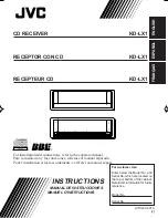
1. After the page loads, the 100e login
page appears (
Figure 9
).
Figure 9. Login Page
2. Login with the default credentials.
“admin” for
Username
and
Password
.
3. Click
Log in
.
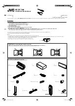
4. Click
OK
in the pop-up to change
the
default password
(
Figure 10
).
Figure 10. Edit Admin Account
Form
5. Now you can access the
Users
page by hovering over
Administration
on the left and
clicking
Users
(
Figure 11
).
Figure 11. Users Page
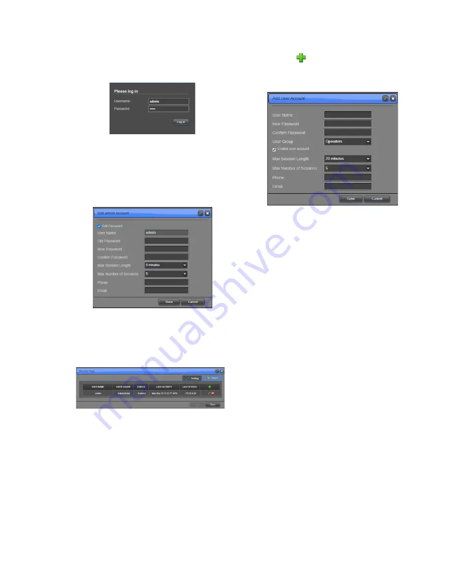
6. Click
to add a user to the
system. The
Add User Account
window appears (
Figure 12
).
Figure 12. Add User Account
Window
7. Type the
User Name
for the
account (case sensitive).
8. Enter a password for the user in
New Password
and the same
password in
Confirm Password
(case sensitive and minimum of
eight characters).
9. For
User Group
, select “Engineers”
from the dropdown.
NOTE:
Engineer accounts can configure the
system while Operators are only able to view
status.
10. Ensure the
Enable user account
check box is selected.
11. Make any other changes to the form
as desired.
12. Click
Save
. The new user now
appears in the
Users
table.
13. Click
Sign out
at the top right of the
page.
E)
Upgrade Firmware
1. To access the Firmware Manager
(
Figure 13
), click the
Upgrade
Firmware
option under the
Administration
section on the side
bar menu.
2. Click
Upload
, then
Browse
to
select the software package to be
installed, and then
Upload
again to
load the package onto the system.
3. Click
Activate
and set the
Firmware Role
to “Primary”.