GatesAir Intraplex IP Link 100e Quick Start Manual Download Page 3

Intraplex

®

 IP Link 100e 

Quick Start Guide v1.0 

Page 

3

 of 

8


Intraplex

® 

IP Link 100e Quick Start 

Guide


Congratulations on purchasing the Intraplex

®

 IP 

Link 100e! This document provides initial setup 
instructions.  

A) 

Installation


You may need to install your IP Link 
100e in a Flexiva Transmitter if you did 
not purchase them together. Otherwise, 
you can skip this section and start with 

Section B. 
 

1.  Remove AC power from Flexiva 

Compact Class Transmitter and 
transport to an ESD safe 
workbench. 

2.  Remove top cover of transmitter 

(

Figure 1

). 


Figure 1. Flexiva Top Cover 


3.  Locate the modulator board in your 

transmitter. This is the large circuit 
card pictured in 

Figure 2


Figure 2. Flexiva Modulator Board 


4.  From the back of the transmitter 

remove the 3 screws securing the 
bottom-most knock out panel. Keep 
these screws as they will be used in 
future steps. Remove the aluminum 
panel and set aside (

Figure 3

). 

Figure 3. Remove Rear Panel 
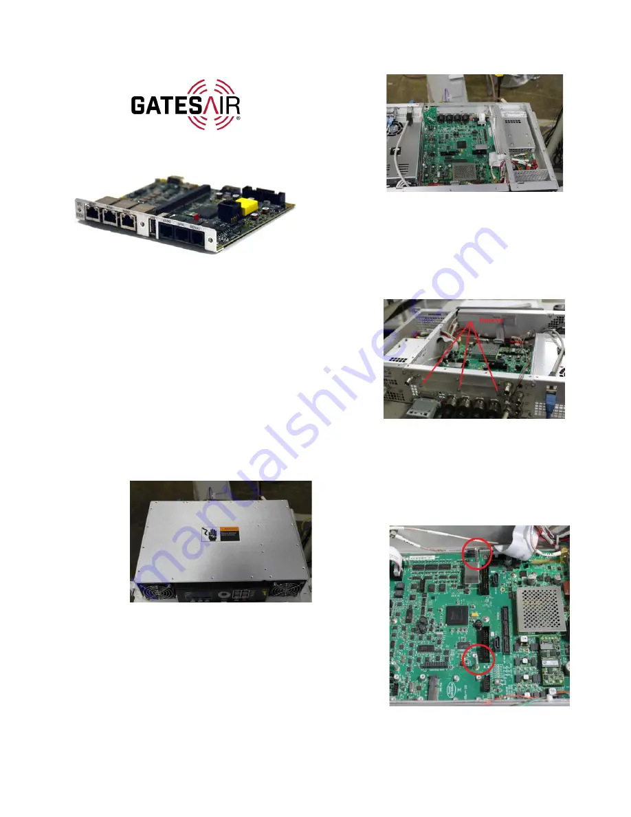
 

5.  (

If there are no other cards 

installed

) Install the two standoffs 

supplied with the kit as shown in 
figure below. The rear of the 100e 
card will sit on top of these in the 
next step (

Figure 4

). 

Figure 4. Install Standoffs 

Without Other Cards 

Summary of Contents for Intraplex IP Link 100e

Page 1: ...IP Link 100e Audio over IP Card For FAX Compact Series Transmitter 888 2944 001 Revision A Oct 2021...

Page 2: ...or an unknown time in the future This publication does not in any way warrant description accuracy or guarantee the use for the product to which it refers GatesAir reserves the right without notice to...

Page 3: ...rkbench 2 Remove top cover of transmitter Figure 1 Figure 1 Flexiva Top Cover 3 Locate the modulator board in your transmitter This is the large circuit card pictured in Figure 2 Figure 2 Flexiva Modu...

Page 4: ...top cover and screw it down B Set Up Network Connection Figure 8 100e Back Panel Connections Connect your IP Link 100e MGMT interface to the desired network See the above picture to identify the inter...

Page 5: ...ter a password for the user in New Password and the same password in Confirm Password case sensitive and minimum of eight characters 9 For User Group select Engineers from the dropdown NOTE Engineer a...

Page 6: ...DHCP to set a static IP Address and Subnet Mask for the connected network 6 Click Apply 7 Enter the newly applied IP address into the browser s address bar as in Section B Step 2 and press enter Note...

Page 7: ...e 18 Figure 18 Stream Creation Window 2 For transmit streams enter the Destination IP address For receive streams no fields require any changes 3 Click Save and the stream will be displayed on the cha...

Page 8: ...Voltage 350 V Max Current 120 mA Max On Resistance 35 Ohms when active Output Contact State Power Off Hi Z Initial Power On Hi Z Normal Hi Z Alarm or Assert Low Z 3 Serial Pin Assignments K Additiona...

Reviews: