


A3 Installation
UltraScan Use
r
’s Guide Reference Series Rev 1.0
XIII
A3.3 Water lines
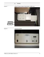
Figure A10 shows how the camera is connected to the microscope’s water-
cooling system. The line used to expel used cooling water from the camera is
called the water-exhaust line and the line used to intake cooling water into the
camera is called the water-intake line. Lines 1, 2, and 3 are in series and take
cooling water to the camera. Lines 4 and 5 return the water to the microscope
water chiller.
•
Cut the water-chiller hose that runs from the water chiller to the
microscope.
The cut must be made before any pressure regulation or flow restriction in
the microscope plumbing. This will insure that once the water-intake line is
installed, the cooling water will be pushed into the water-intake line so that
the water can cool the camera.
•
Insert a supplied T into the previously cut hose.
Choose the size of T that best fits the water-chiller hose. Screw-type hose
clamps can be used to secure the T to the two ends of the hose.
•
Cut the water-chiller hose that runs from the microscope to the water
chiller.
The cut must be made after any pressure regulation or flow restriction in
the microscope plumbing. This will insure that once the water exhaust line
is installed, the thermally degraded cooling water will be pushed out of the
water-exhaust line so that the water will not return to the camera.
•
Insert a supplied T into the water-chiller hose that runs from the
microscope to the water chiller.
Choose the size of T that best fits the water-chiller hose. Screw-type hose
clamps can be used to secure the T to the two ends of the hose.
•
Connect line 5 to the inserted T.
A screw-type hose clamp can be used to secure the line to the hose.
•
Set the pressure regulator to obtain a flow of 10-12 L/hr within the
limits imposed by the microscope water chiller and the flow needed by
the diffusion pump.
•
Set the chiller temperature regulator around 20-23
°
C.
Note that temperatures lower than 20
°
C may result in condensation
accumulating in the CCD camera head electronics. This may interfere with
normal functioning of the camera.
•
Connect line 1 to the pressure regulator end of line 2.


