


Part 10 - Lighting the appliance / First start-up
Left
Mean value of
Extra information (on the
right)
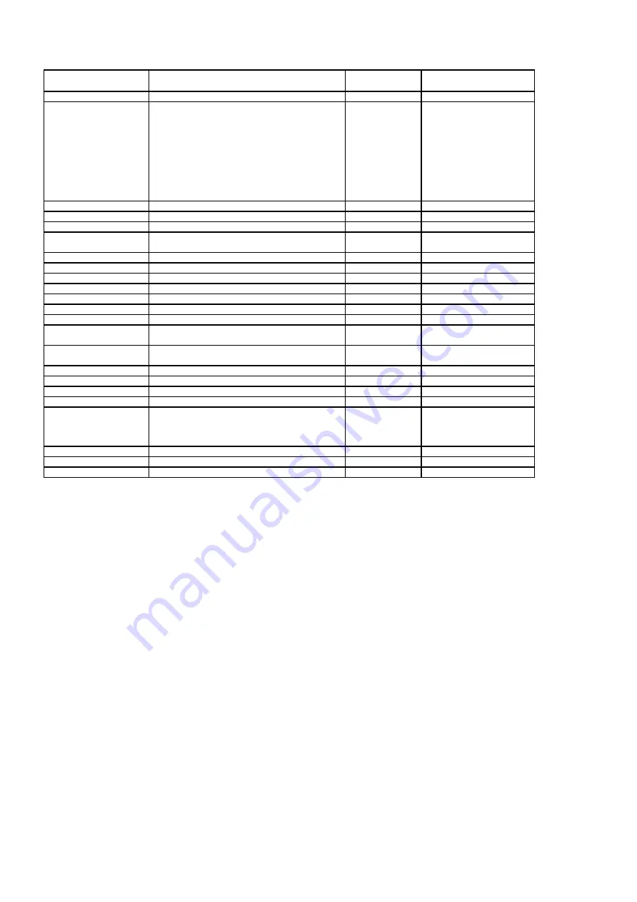
0
Software version
-
So
1
Heat exchanger mode:
0 rest
2 start fan
3 pre ventilation
4 ignition
5 CH operation
6 DHW operation
7 heat up tap exchanger
8 anti-swing waiting time
2
Modulation level flame + %
Flame + %
-
3
CH pressure
Bar / PSI
P1
4
CH supply temperature
°C / °F
t1
5
Set point supply temperature
°C / °F
t1 < > SP
CH
6
CH return temperature
°C / °F
t2
7
DHW flow sensor
l / minute
F1
8
DHW temperature
°C/ °F
t3
9
Setpoint DHW temperature
°C/ °F
t3 < > SP
10
Flue gas temperature
°C/ °F
t4
11
Outside temperature
°C/ °F
t5
12
Temperature Tank
°C/ °F
t6
21
Room temperature (of
°C/ °F
rt
OpenTherm® thermostat)
22
Setpoint room temperature
°C/ °F
rt < > SP
(of OpenTherm® thermostat)
24
Modulation pump
%
bP
29
Gasvalve modulation current
mA
I = current
30
Flame resistance (actual value)
kOhm
FL = flame
31
Fan speed
rpm
-
32
Calibration done
-
CAL = calibration
Completed
--- = calibration not
completed, Do Calibration
33
Flame resistance setpoint 0%
kOhm
FL
34
Flame resistance setpoint ignition speed
kOhm
FL
35
Flame resistance setpoint 100%
kOhm
FL
°C/ °F = °C is for older boilers that have LCD screen with SKU sticker CP37.02
°F is for new boilers that have LCD screen with SKU sticker CP37.03
Table 10.2 Diagnose menu
65