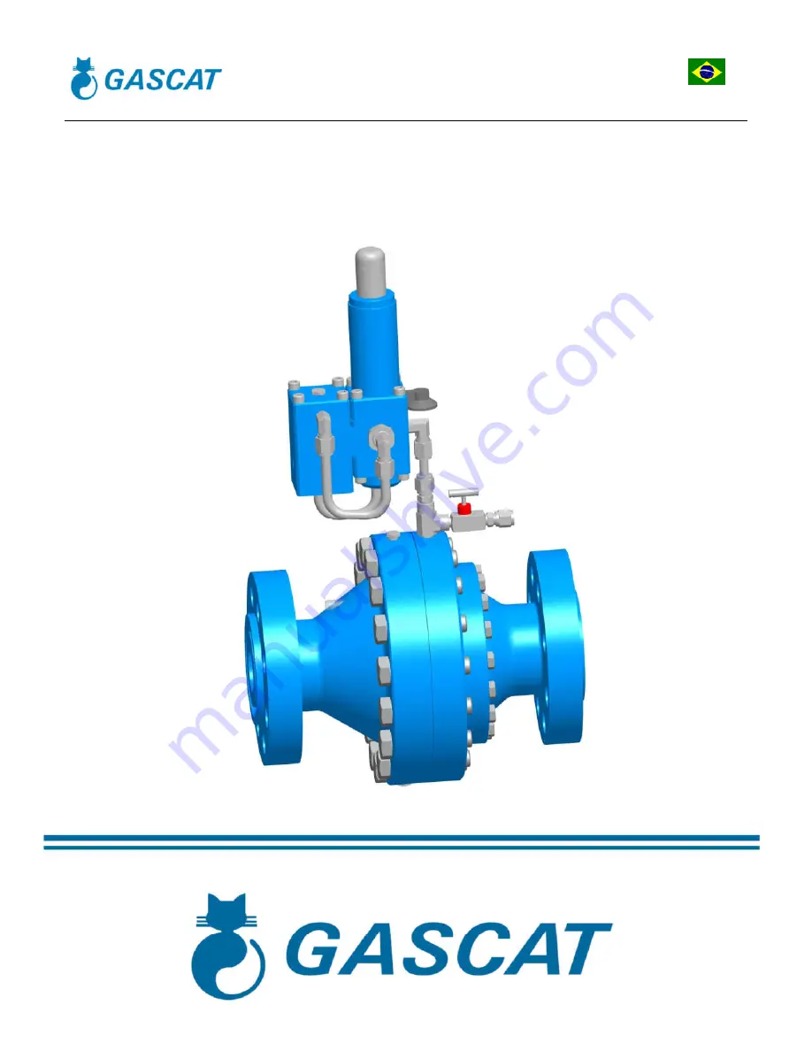
Installation Manual, Maintenance and Operation
Pressure Regulating Valve
Model HORUS Spring to Close
Page 1: ...Installation Manual Maintenance and Operation Pressure Regulating Valve Model HORUS Spring to Close...
Page 2: ...2 3 8 ACCURACY AND LOCK UP 7 3 0 PRINCIPLE OF OPERATION 7 3 1 REGULATOR SPRING TO CLOSE FAIL CLOSE 7 3 2 BOOSTER G 43 9 3 3 PILOTS G 40 G 42 10 3 4 FILTERS 11 4 0 INSTALLATION 11 4 1 FILTER 11 4 2 CLE...
Page 3: ...3936 9300 Fax 55 19 3935 6009 Email sales gascat com br The comments that follow while not exhaustive provide guidance possible sources of danger to health and safety 1 2 1 NOISE Regulators valves an...
Page 4: ...te the high pressure device since high pressures can be retained downstream of isolation valves Do not try to remove covers plugs etc before this device is properly released Still it is wise to consid...
Page 5: ...RF 600 RF ou RTJ 900 RF ou RTJ PN 25 PN 40 8 150 RF 300 RF 600 RF ou RTJ 900 RF ou RTJ PN 25 PN 40 10 150 RF 300 RF 600 RF ou RTJ 900 RF ou RTJ PN 25 PN 40 2 3 3 TEMPERATURE LIMITS Operating temperat...
Page 6: ...40 19 bar 51 bar 100 bar 150 bar 25 bar 40 bar Pressure limits reported in this manual or any standard should not be exceeded under any circumstances at the risk of damage to the equipment installatio...
Page 7: ...the gas feeding pressure with the outlet pressure sensed by the pilot diaphragm H and controls the flow to be injected under the main regulator diaphragm L If a decrease in downstream pressure occurs...
Page 8: ...ual Maintenance and Operation Pressure Regulating Valve Model Horus MI 18 Elaborate Verified Approved CSQ Date Review Page J Junior Celso Nieto JM 25 11 16 04 8 de 32 FIGURE 1 HORUS FAIL CLOSED F A D...
Page 9: ...nt e g if we are adjusting the pressure regulator to 20 bar the booster will be applying to the pilot a pressure of 21 to 22 bar Typically the booster G 43 have three connections to the process These...
Page 10: ...gulating valves open or close under normal process conditions by the balance between the force of the regulating spring and the outlet pressure received by the sensor outlet The green line represents...
Page 11: ...e control Care for the filter installation is essential to the smooth operation of the instrument as any existing particles in the pipe can become lodged between the seat and the shutter damaging them...
Page 12: ...a better pneumatic signal use OF tubbings stainless steel AISI 316 to connect the regulator to the process In order to avoid the accumulation of impurities and condensate in the impulse taken recommen...
Page 13: ...tput block valve 5 Pressure regulator valve model URANO GASCAT Note The position indicated for the sensor outlet may be less than 5D from the installation project to be reviewed and approved by engine...
Page 14: ...n ATTENTION Under no circumstances do with the line pressurization where the equipment is installed by the posterior valve equipment Under any circumstances perform depressurization line where equipme...
Page 15: ...Check that the pilot of the regulating spring is properly relieved discharged Relieving regulating spring we are ensuring that the valve will remain in the closed position when pressurized 3 Make sur...
Page 16: ...at you performed the same procedure reported in 4 6 2 but the set point pressure regulator should be adjusted for a 15 pressure 20 less than the valve set point that is in operation Made it open SLOWL...
Page 17: ...be from different situations but most of them is related to the gas conditions impurities natural wear and failures during operation of the equipment It is important to keep in mind that the operation...
Page 18: ...e it if necessary Headquarters pos 44 SO pos 38 SC damaged or particulate matter between the shutter and the seat Make cleaning and check state headquarters if it has no apparent marks of damage proce...
Page 19: ...ensate etc certainly the service interval should be lower The GASCAT own standards repair kits for each throttle component URANO model composed of the most likely items to wear with time this list of...
Page 20: ...al Maintenance and Operation Pressure Regulating Valve Model Horus MI 18 Elaborate Verified Approved CSQ Date Review Page J Junior Celso Nieto JM 25 11 16 04 20 de 32 6 1 RECOMMENDED REPAIR PARTS AND...
Page 21: ...Page J Junior Celso Nieto JM 25 11 16 04 21 de 32 HORUS SC FF POS DESCRIPTION DN 1 2 3 4 6 8 1 DIAPHRAGM 1 1 1 1 1 1 3 POSITION INDICATION DISPLAY 1 1 1 1 1 1 8 O RING 1 1 1 1 1 1 9 O RING 1 1 1 1 1...
Page 22: ...llation Manual Maintenance and Operation Pressure Regulating Valve Model Horus MI 18 Elaborate Verified Approved CSQ Date Review Page J Junior Celso Nieto JM 25 11 16 04 22 de 32 BOOSTER G 43 PILOT G...
Page 23: ...roved CSQ Date Review Page J Junior Celso Nieto JM 25 11 16 04 23 de 32 BOOSTER G 43 POS DESCRI O QTY 8 GARRISON 1 10 DIAPHRAGM 1 18 O RING 1 20 O RING 1 21 O RING 1 22 O RING 1 25 O RING 1 PILOTO G 4...
Page 24: ...ieto JM 25 11 16 04 24 de 32 G 80 PILOT CODE 28 21 28A_KIT POS DESCRIPTION QTY POS DESCRIPTION QTY 1 RELIEF 2 11 O RING 1 2 DIAPHRAGM 1 12 O RING 1 3 DIAPHRAGM 1 13 O RING 2 4 SHUTTER 1 14 O RING 1 5...
Page 25: ...ssembly of equipment if it is pressurized The disassembly procedure below references the positions of the components shown in the diagram available in section 6 0 of this manual 3 Download the pilot r...
Page 26: ...ve the bushing item 34 31 shutter spring 10 Remove the obturator pos 29 26 11 Remove the diaphragm plate and the lower diaphragm pos 9 11 turn the steering block to the starting position and proceed w...
Page 27: ...the seat pos 46 48 in the mobile Pos 44 46 is necessary to leave the perfectly aligned to the mobile base of the hole headquarters in order to prevent the same into contact with the walls of the mobil...
Page 28: ...the disassembly of the equipment check if all the conditions set out in item 4 6 1 of this manual have been observed 2 Go up any circumstances start the disassembly of equipment if the same is pressur...
Page 29: ...ate Verified Approved CSQ Date Review Page J Junior Celso Nieto JM 25 11 16 04 29 de 32 1 Remove the cover pos 39 and the diaphragm assembly item 28 2 Lock the shaft pos 28 release the nut pos 11 remo...
Page 30: ...unior Celso Nieto JM 25 11 16 04 30 de 32 3 Now let s move to dismantle the bottom of the booster so the ideal is that it is rotated so that the bottom is face up made it proceed with the removal of t...
Page 31: ...but would like to make some observations on some specific points that must be evaluated thoroughly during reassembly of the booster 1 When installing the axis diaphragm assembly item 28 is necessary t...
Page 32: ...egulating Valve Model Horus MI 18 Elaborate Verified Approved CSQ Date Review Page J Junior Celso Nieto JM 25 11 16 04 32 de 32 6 6 LIST OF RECOMMENDED TOOLS FOR MAINTENANCE TOOLS DIMENSIONS KEY COMBI...