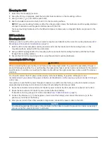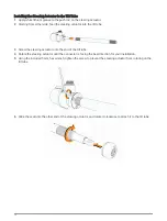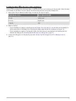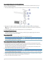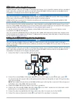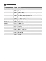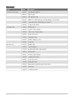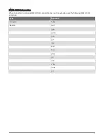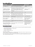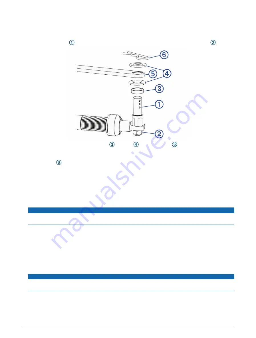
Connecting the Linkage Arm to the Steering Actuator
After you connect the linkage arm to your kicker motor tiller arm using the appropriate bracket, you must
connect it to the steering actuator.
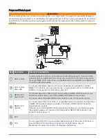
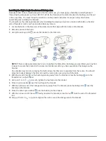
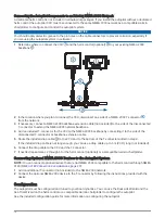
1 Screw the linkage pin into the end of the steering actuator rod, and secure it with the lock nut .
2 Referring to the diagram, install the spacer , washers
, and linkage arm onto the linkage pin.
NOTE: You can install an additional black spacer (included) on the linkage pin if needed to help level the
linkage arm.
3 Push the R-pin through the hole on the linkage pin to secure the linkage arm.
Installing the Throttle Actuator
Follow the throttle actuator installation instructions provided with your autotpilot system to mount the
actuator and connect it to the motor throttle.
Connecting the CCU
Route the connector end of the CCU cable to the ECU and make the connection.
NOTICE
You should apply dielectric grease to the pin holes on the cable connector to prevent corrosion, especially if
you are using the autopilot system in saltwater.
Connecting the Drive Actuator and Throttle Actuator
You should install the drive actuator and throttle actuator on the motor before connecting them to the ECU.
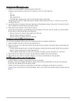
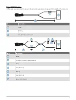
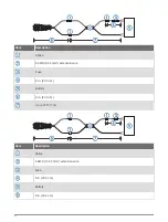
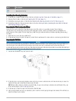
1 Route the drive actuator cable to the drive actuator and to the ECU, and make sure there is enough slack in
the cable to allow for the motor to turn fully port and starboard.
This cable cannot be extended, so if it is not long enough, you must relocate the ECU, extending the ECU
power cable if necessary (
Power Cable Extensions, page 9
).
2 Connect the drive actuator cable to the drive actuator and to the ECU.
NOTICE
You should apply dielectric grease to the pin holes on the cable connector to prevent corrosion, especially if
you are using the autopilot system in saltwater.
3 Route the throttle actuator cable from inside the motor housing to the ECU, and make sure there is enough
slack in the cable to allow for the motor to turn fully port and starboard.
4 Connect the throttle actuator cable to the ECU.
16

