190-01007-A1
System Maintenance Manual GTN 6XX/7XX Part 23 AML STC
Rev. 5
Page A-5
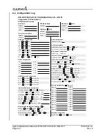
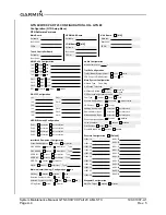
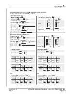
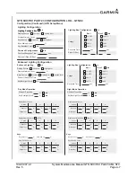
GTN 6XX/7XX PART 23 CONFIGURATION LOG - GTN #1
Configuration (Continued) (GTN Setup Menu)
Photocell Slope/Offset:
Photocell Response Time:
sec.
Photocell Configuration
N/A
/
Lighting Configuration
Lighting Configuration
Display Source:
Lighting Bus 1
Photocell
Keys Source:
Display Minimum Level:
%
%
Keys Minimum Level:
Lighting Bus 1
Photocell
Key Backlight Cutoff:
N/A
Lighting Bus Configuration
N/A
Bus 1
Bus 2
N/A
Voltage
Response Time
Slope / Offset
14 VDC
28 VDC
5 VDC
5 ADC
14 VDC
28 VDC
5 VDC
5 ADC
sec.
sec.
/
/
N/A
Lighting Bus Configuration
N/A
Bus 1
Bus 2
N/A
Voltage
Response Time
14 VDC
28 VDC
5 VDC
5 ADC
14 VDC
28 VDC
5 VDC
5 ADC
sec.
sec.
Enhanced Lighting
Display Source:
Lighting Bus 1
Photocell
Keys Source:
Display Minimum Level:
%
sec.
Photocell Response Time:
Lighting Bus 1
Photocell
Key Backlight Cutoff:
N/A
N/A
Lighting Bus 2
Night Mode Operation
Photocell Transition:
%
N/A
Key Backlight Cutoff:
%
N/A
Day Mode Operation
Photocell Transition:
%
N/A
Key Backlight Cutoff:
%
N/A
Display Source Curve
Vertex
Input Lvl
Output Lvl
1
2
3
4
%
%
%
%
%
%
%
%
Display Photocell Curve
Vertex
Input Lvl
Output Lvl
%
%
%
%
%
%
%
%
[
N/A
]
Keys Source Curve
Vertex
Input Lvl
Output Lvl
%
%
%
%
%
%
%
%
Keys Max Lvl:
%
Keys Min Lvl:
%
Keys
Display Source Curve
Vertex
Input Lvl
Output Lvl
%
%
%
%
%
%
%
%
Display Photocell Curve
Vertex
Input Lvl
Output Lvl
%
%
%
%
%
%
%
%
[
N/A
]
Keys Source Curve
Vertex
Input Lvl
Output Lvl
%
%
%
%
%
%
%
%
Keys Max Lvl:
%
Keys Min Lvl:
%
Keys
1
2
3
4
1
2
3
4
1
2
3
4
1
2
3
4
1
2
3
4
Enhanced Lighting Configuration
Lighting Configuration

