190-01007-A1
System Maintenance Manual GTN 6XX/7XX Part 23 AML STC
Rev. 5
Page 7-17
7.4.3.4 EHSI Deviation Scaling for HSI/CDI Driven by GTN via ARINC 429 Data
If the GTN has a serial connection to an EFIS display, proper scaling of the EFIS CDI and VDI must be
verified.
1. Cycle power to the GTN and acknowledge the prompts until it gets to the Instrument Panel Self-
Test page (see Section 6.1.1).
2. With the Instrument Panel Self-Test page displayed on the GTN, look on the EHSI/EFIS and
verify that the lateral deviation is half-scale left and not flagged.
3. With the Instrument Panel Self-Test page displayed on the GTN, look on the EHSI/EFIS and
verify that the vertical deviation is half-scale up and not flagged.
7.4.3.5 GMX200/MX20 Interface Check
The Garmin GMX 200 or MX20 interface should be verified as described in this section.
1. Ensure that the GTN has a 3-D position fix.
2. Create and activate a flight plan on the GTN by touching the
Direct-To
key and entering a
waypoint.
3. Verify that the RTE and POS data flags are not displayed on the GMX 200/MX20.
4. Verify that the flight plan is displayed on the GMX 200/MX20 using the flight plan (FPL)
function.
7.4.4 Transponder
1. For remote transponders, configure transponder per Section 7.4.4.1.
2. Perform interface check per Section 7.4.4.2.
7.4.4.1 Remote Transponder Configuration
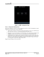
A remote transponder can be configured by the GTN via RS-232 if a transponder is configured for one of
the RS-232 ports. To configure the transponder, it must first be selected as present and the type of
transponder installed must be specified. To do this, access the
Interfaced Equipment
page on the GTN
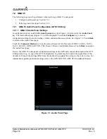
Setup page (Figure 3-11). Next, go to the External Systems page and touch the
XPDR
key. This displays
the page shown in Figure 7-4, which allows the remote transponder to be configured. The remote
transponder should be configured in accordance with the installation manual for that specific transponder.
NOTE
If the GTN controls any transponder (GTX 32/33/327/328/330), then that transponder will
boot into the same mode (Normal or Configuration) as the GTN.
NOTE
If the GTN is not communicating with the GTX transponder, all of the editable fields for
the setup items shown in the following sections will be dashed out. If the fields are dashed
out, check the wiring and pin connections from the GTN to the transponder.
NOTE
The GTN can interface to the GTX 327/328/330/330 ES; however, configuration of the
panel-mounted GTX 327/328/330/330 ES is not supported. These transponders should be
configured per their installation manuals rather than through the GTN.

