background image

You can also open the sonar alarms by selecting 

Settings

 > 

Alarms

 > 

Sonar

.

Shallow Water

: Sets an alarm to sound when the depth is less 

than the specified value.

Deep Water

: Sets an alarm to sound when the depth is greater 

than the specified value.

FrontVü Alarm

: Sets an alarm to sound when the depth in front 

of the vessel is less than the specified value, which can help 

you avoid running aground (

Setting the FrontVü Depth Alarm

page 26

). This alarm is available only with Panoptix FrontVü 

transducers.

Water Temp.

: Sets an alarm to sound when the transducer 

reports a temperature that is 2°F (1.1°C) above or below the 

specified temperature.

Contour

: Sets an alarm to sound when the transducer detects a 

suspended target within the specified depth from the surface 

of the water and from the bottom.

Fish

: Sets an alarm to sound when the device detects a 

suspended target.

 sets the alarm to sound when fish of all sizes are 

detected.

 sets the alarm to sound only when medium or large 

fish are detected.

 sets the alarm to sound only when large fish are 

detected.

Advanced Sonar Settings

From a Traditional sonar view, select 

Menu

 > 

Sonar Setup

 > 

Advanced

.

Shift

: Allows you to set the depth range on which the sonar is 

focused. This allows you to zoom in a higher resolution in the 

focused depth.
When using shift, bottom tracking may not work effectively, 

because the sonar looks for data within the depth range of 

the focused area, which may not include the bottom. Using 

shift also can impact the scroll speed, because data outside 

the depth range of the focused area is not processed, which 

reduces the time required to receive and display the data. 

You can zoom in to the focused area, which enables you to 

evaluate target returns more closely at a higher resolution 

than just zooming alone.
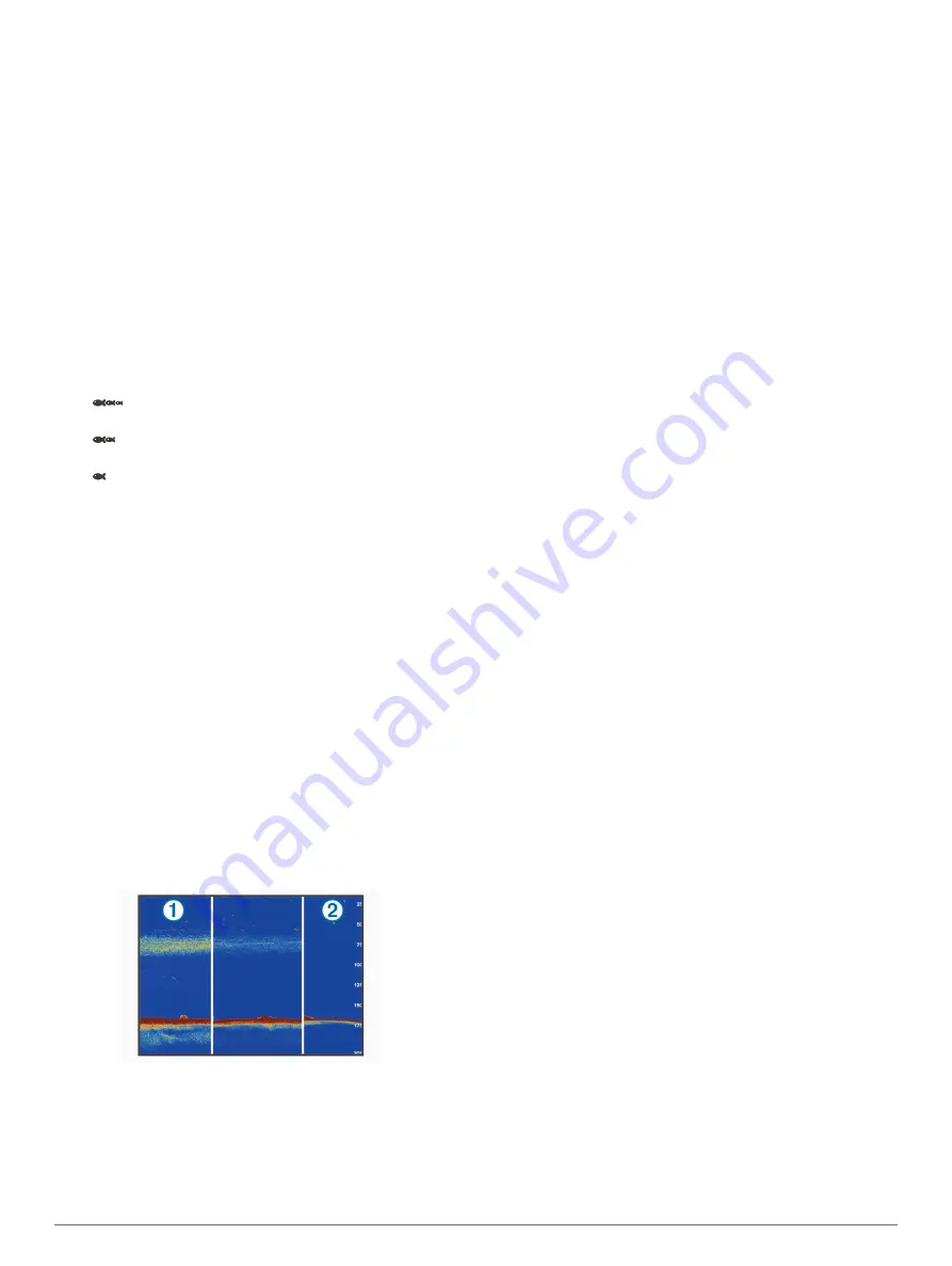
Echo Stretch

: Adjusts the size of the echoes on the screen to 

make it easier to see separate returns on the screen.
When targets are difficult to see 

À

, echo stretch makes the 

target returns more pronounced and easier to see on the 

screen. If the echo stretch value is too high, the targets blend 

together. If the value is too low 

Á

, the targets are small and 

more difficult to see.

You can use echo stretch and filter width together to obtain 

the preferable resolution and noise reduction. With echo 

stretch and filter width set to low, the display has the highest 

resolution, but is the most susceptible to noise. With echo 

stretch set to high and filter width set to low, the display has a 

lower resolution, but has wider targets. With echo stretch and 

filter width set to high, the display has the lowest resolution, 

but is the least susceptible to noise. It is not recommended to 

set echo stretch to low and filter width to high.

Traditional, Garmin ClearVü, and SideVü Transducer 

Installation Settings

From a Traditional, Garmin ClearVü, or SideVü sonar view, 

select 

Menu

 > 

Sonar Setup

 > 

Installation

.

Transmit Rate

: Sets the length of time between sonar pings. 

Increasing the transmit rate increases the scroll speed, but it 

may also increase self-interference.
Reducing the transmit rate increases the spacing between 

transmit pulses and can resolve self-interference. This option 

is available on the Traditional sonar view only.

Transmit Power

: Reduces transducer ringing near the surface. 

A lower transmit power value reduces transducer ringing, but 

can also reduce the strength of the returns. This option is 

available on the Traditional sonar view only.

Filter Width

: Defines the edges of the target. A shorter filter 

more clearly defines the edges of the targets but may allow 

more noise. A longer filter creates softer target edges and 

may also reduce noise. This option is available on the 

Traditional sonar view only.

Flip Left/Right

: Switches the SideVü view orientation from left 

to right. This option is available on the SideVü sonar view 

only.

Restore Sonar Defaults

: Restores the sonar settings to the 

factory default values.

Transducer Diagnostics

: Shows details about the transducer.

Sonar Frequencies

NOTE: 

The frequencies available depend on the chartplotter, 

sounder modules, and transducer being used.
Adjusting the frequency helps adapt the sonar for your particular 

goals and the present depth of the water.
Higher frequencies use narrow beam widths, and are better for 

high-speed operation and rough sea conditions. Bottom 

definition and thermocline definition can be better when using a 

higher frequency.
Lower frequencies use wider beam widths, which can let the 

fisherman see more targets, but could also generate more 

surface noise and reduce bottom signal continuity during rough 

sea conditions. Wider beam widths generate larger arches for 

fish target returns, making them ideal for locating fish. Wider 

beam widths also perform better in deep water, because the 

lower frequency has better deep water penetration.
CHIRP frequencies allow you to sweep each pulse through a 

range of frequencies, resulting in better target separation in 

deep water. CHIRP can be used to distinctly identify targets, like 

individual fish in a school, and for deep water applications. 

CHIRP generally performs better than single frequency 

applications. Because some fish targets may show up better 

using a fixed frequency, you should consider your goals and 

water conditions when using CHIRP frequencies.
Some sonar black boxes and transducers also provide the ability 

to customize preset frequencies for each transducer element, 

which enables you to change the frequency quickly using the 

presets as the water and your goals change.
Viewing two frequencies concurrently using the split-frequency 

view allows you to see deeper with the lower frequency return 

and, at the same time, see more detail from the higher 

frequency return.

Selecting Frequencies

NOTE: 

You cannot adjust the frequency for all sonar views and 

transducers.
You can indicate which frequencies appear on the sonar screen.

1

From a sonar view, select 

Menu

 > 

Frequency

.

Sonar Fishfinder

25

Summary of Contents for GPSMAP 8500

Page 1: ...GPSMAP 8000 8500SERIES Owner sManual...

Page 2: ...min Connect Garmin Express Garmin Helm Garmin LakeV Garmin Nautix Garmin Quickdraw GCV GMR GRID GXM HomePort MotionScope OneChart Panoptix Shadow Drive and SmartMode are trademarks of Garmin Ltd or it...

Page 3: ...ting a Target for an AIS Vessel 8 Viewing a List of AIS and MARPA Threats 8 Setting the Safe Zone Collision Alarm 8 AIS Distress Signals 8 Navigating to a Distress Signal Transmission 8 AIS Distress S...

Page 4: ...n of Sonar Signals 20 Changing the Sonar View 20 Traditional Sonar View 20 Split Frequency Sonar View 20 Split Zoom Sonar View 20 Garmin ClearV Sonar View 20 SideV Sonar View 20 SideV Scanning Technol...

Page 5: ...to a Vessel in Distress 34 Man Overboard Distress Calls Initiated from a VHF Radio 34 Man Overboard and SOS Distress Calls Initiated from the Chartplotter 34 Position Tracking 35 Viewing a Position R...

Page 6: ...ion Chart 43 Weather Overlay Settings on the Fishing Chart 43 Viewing Weather Subscription Information 43 Viewing Video 43 Selecting a Video Source 43 Alternating Among Multiple Video Sources 43 Netwo...

Page 7: ...Chartplotter 52 Pairing the GRID Device with the Chartplotter from the Chartplotter 52 Pairing the GRID Device with the Chartplotter from the GRID Device 52 Rotating the GRID Joystick 52 Cleaning the...

Page 8: ......

Page 9: ...menu Turns on and off the radar echo trails Acquires a radar target and begins tracking it Shows and sets the VRM EBL line Opens the menu for the page or function Opens the Weather menu for the page...

Page 10: ...reen you can return to the home screen by selecting Home When multiple displays are installed on the Garmin Marine Network you can group them together into a station A station enables the displays to...

Page 11: ...n navigating select Navigation and select an option To turn on other data bars like the media controls select Top Bar or Bottom Bar and select the necessary options 3 Select Done Resetting the Station...

Page 12: ...er Garmin Quickdraw contours you have downloaded or created Yes Push smart notifications Yes Yes Automatically transfer user data such as waypoints and routes Yes Begin navigating to a specific waypoi...

Page 13: ...2 Enter a new channel You do not need to change the wireless channel of devices connected to this network Changing the Wi Fi Host You can change which chartplotter is serving as the Wi Fi host The can...

Page 14: ...rect course and a corrected course may pass over land or shallow water Use visual sightings and steer to avoid land shallow water and other dangerous objects NOTE The Fishing chart is available with p...

Page 15: ...the land Select Photo Map to show photos on both the water and the land at a specified opacity Use the slider bar to adjust the photo opacity The higher you set the percentage the more the satellite...

Page 16: ...to include in the list Setting the Safe Zone Collision Alarm Before you can set a collision alarm you must have a compatible chartplotter connected to an AIS device or radar The safe zone collision a...

Page 17: ...yer Depth Layer Settings page 9 Depth Layer Settings From a chart select Menu Layers Chart Depth Depth Shading Specifies an upper and lower depth to shade between Shallow Shading Sets the shades from...

Page 18: ...enu Layers Radar From a radar screen select Menu Radar To Standby Stops radar transmission Gain Adjusts the gain Adjusting Gain on the Radar Screen Automatically page 30 Sea Clutter Adjusts the sea cl...

Page 19: ...been shared for that area 3 Select Select Download Region 4 Drag the box to select the area to download 5 Drag the corners to change the download area 6 Select Download Area The next time you connect...

Page 20: ...eed above 32 km h 20 mph Depth Shading Specifies the minimum and maximum depths of a depth range and a color for that depth range Depth Range Shading You can set color ranges on your map to show the w...

Page 21: ...from the Navigation or Fishing chart select an option Select Menu Stop Navigation When navigating with Auto Guidance select Menu Navigation Options Stop Navigation Waypoints Waypoints are locations yo...

Page 22: ...cation of your vessel The last turn you add should be the first turn you make starting from your present location It should be the turn closest to your vessel 6 If necessary select Menu 7 Select Done...

Page 23: ...Destinations page 13 2 Select Navigate To Auto Guidance 3 Review the path indicated by the magenta line 4 Select Start Navigation 5 Follow the magenta line steering to avoid land shallow water and ot...

Page 24: ...ance setting to Near or Nearest As a result the chartplotter may not reposition the Auto Guidance line unless the destination selected requires navigation through a narrow waterway 8 Select an option...

Page 25: ...the map You can also convert saved tracks and routes into boundary lines You can create a boundary area using waypoints by creating a route from the waypoints and converting the route into a boundary...

Page 26: ...art Line 2 Select an option To mark the port and starboard starting line marks as you sail past them select Ping Marks To mark the port and starboard starting line marks by entering their coordinates...

Page 27: ...advanced autopilot configuration see the installation instructions included with your autopilot 1 From the autopilot screen select Menu Autopilot Setup Wind Hold Type 2 Select Apparent or True Engagi...

Page 28: ...the split frequency view you can separately adjust the gain for each frequency If you do not see an arrangement of sonar views to suit your needs you can create a custom combination screen Creating a...

Page 29: ...l around the boat in real time You can also watch your bait underwater and bait schools in front of or below your boat The LiveV sonar views provide you a view of the live movement either in front of...

Page 30: ...equency transducer select Dual Frequency 200 50 kHz If you have another type of transducer select it from the list Calibrating the Compass Before you can calibrate the compass the transducer must be i...

Page 31: ...as of interest on the sonar screen by adjusting the color gain for traditional transducers or the contrast for Garmin ClearV and SideV ClearV transducers This setting works best after you have adjuste...

Page 32: ...to adjust the range automatically select Auto To increase or decrease the range manually select Up or Down TIP From the sonar screen you can select or to manually adjust the range TIP When viewing mu...

Page 33: ...allation Transmit Rate Sets the length of time between sonar pings Increasing the transmit rate increases the scroll speed but it may also increase self interference Reducing the transmit rate increas...

Page 34: ...difficult to recognize actual returns Depth Range Adjusts the range of the depth scale Allowing the device to adjust the range automatically keeps the bottom within the lower portion of the sonar scr...

Page 35: ...V LiveV Forward and RealV 3D Forward sonar views Beam Width Sets the width of the down view Panoptix transducer beam Narrow beam widths allow you to see deeper and farther Wider beam widths allow you...

Page 36: ...he radar enters standby mode after it warms up This gives you an opportunity to verify the area around the radar is clear before beginning radar transmission 1 With the chartplotter off connect your r...

Page 37: ...the location of the outer guard zone corner 3 Select Corner 2 4 Touch the location of the inner guard zone corner to define the width of the guard zone 5 Select Done Disabling a Guard Zone You can dis...

Page 38: ...M EBL 3 Select Stop Pointing Measuring the Range and Bearing to a Target Object Before you can adjust the VRM and the EBL you must show them on the Radar screen Showing the VRM and the EBL page 30 1 F...

Page 39: ...on the Radar Screen Manually You can adjust the appearance of clutter caused by choppy sea conditions The sea clutter setting affects the appearance of nearby clutter and targets more than it affects...

Page 40: ...n which the radar does not transmit signals Enabling and Adjusting a Radar No Transmit Zone page 28 Front of Boat Offset The front of boat offset compensates for the physical location of the radar sca...

Page 41: ...topilot activates Shadow Drive mode When you release the helm and manually maintain a specific heading for a few seconds the autopilot resumes a heading hold at the new heading Adjusting the Heading w...

Page 42: ...up and send individual routine call details to your Garmin VHF radio When you initiate a man overboard distress call from your radio the chartplotter shows the man overboard screen and prompts you to...

Page 43: ...four hours old appear for all tracked vessels Individual Routine Calls When you connect the chartplotter to a Garmin VHF radio you can use the chartplotter interface to set up an individual routine c...

Page 44: ...ms 1 From the engine gauges screen select Menu Installation Status Alarms Custom 2 Select one or more engine gauge alarms to turn on or off Setting the Fuel Alarm Before you can set a fuel level alarm...

Page 45: ...sources of power such as solar alternator converter and wind generator are listed along the left side The items along the right side of the screen are devices that use the batteries and other power s...

Page 46: ...ources 2 Select a source Playing Music Browsing for Music 1 From the media screen select Browse or Menu Browse 2 Select Select or select an option Enabling Alphabetical Search You can enable the alpha...

Page 47: ...scan for DAB stations When the re scan is complete the system starts playing the first station in the ensemble you were listening to when you started the re scan Changing DAB Stations 1 Select the DA...

Page 48: ...usXM Radio Before you can clear all locked channels the parental controls must be unlocked 1 From the media screen select Browse Parental Clear All Locked 2 Enter your passcode Setting the Device Name...

Page 49: ...l pass as received from the weather data provider Weather Warnings and Weather Bulletins When a marine weather warning weather watch weather advisory weather bulletin or other weather statement is iss...

Page 50: ...shading indicates the surface temperature of the water as shown in the legend in the corner of the display Forecasting Fish Locations You can show areas that contain optimal weather conditions for sp...

Page 51: ...the amount of time each video appears 3 Select Source and select the video sources to add to the alternating sequence Networked Video Devices NOTICE A Garmin Power over Ethernet PoE Isolation Coupler...

Page 52: ...gestures allows video control without displaying the video controls 1 From a video screen touch the screen 2 Select an option To zoom in and out with the camera use pinch and zoom gestures To pan or...

Page 53: ...Photo Takes a still photograph Sleep Puts the VIRB action camera into a low power mode to conserve battery power VIRB Action Camera Video Setup Settings Select A V Gauges Controls VIRB Menu Video Set...

Page 54: ...u can view the software version the basemap version all supplemental map information if applicable the software version for an optional Garmin radar if applicable and the unit ID number You may need t...

Page 55: ...n obstacles select Settings Preferences Navigation Auto Guidance Shoreline Distance Far If the turns in the Auto Guidance line are too wide select Settings Preferences Navigation Auto Guidance Shoreli...

Page 56: ...rom an applicable sonar view select Menu Sonar Setup Alarms You can also open the sonar alarms by selecting Settings Alarms Sonar Shallow Water Sets an alarm to sound when the depth is less than the s...

Page 57: ...e measured in step 1 from the water temperature measured in step 2 This is the temperature offset Enter this value in step 5 as a positive number if the sensor connected to the chartplotter measures t...

Page 58: ...nly boundary files with an adm extension are supported 1 Insert a memory card into a card slot 2 Select Info User Data Data Transfer 3 If necessary select the memory card to copy data to 4 Select an o...

Page 59: ...o www garmin com support software marine html select See All Devices in this Bundle and compare the installed software version to the software version listed for your product If the software on your d...

Page 60: ...he memory card 3 Copy a bmp file from the card and paste it to any location on the computer Troubleshooting My device will not acquire GPS signals If the device is not acquiring satellite signals ther...

Page 61: ...rent draw at 12 Vdc 1 3 A Max current draw at 12 Vdc 2 8 A Compass safe distance 310 mm 12 2 in Twelve inch models Dimensions W H D 333 247 97 mm 137 64 923 32 313 36 in Display size W H 245 184 mm 92...

Page 62: ...D Bearing origin to destination GPBWC BWC Bearing and distance to waypoint GPGGA GGA Global positioning system fix data GPGLL GLL Geographic position latitude and longitude GPGSA GSA GNSS DOP and acti...

Page 63: ...inations navigation chart 13 selecting 13 device cleaning 52 registration 51 digital selective calling 34 35 channels 35 contacts 34 individual routine call 35 turning on 34 49 digital switching 51 di...

Page 64: ...adow Drive enabling 33 sharing data 50 shoreline distance 16 47 SideV 20 SiriusXM 38 40 Satellite Radio 39 SiriusXM Satellite Radio 39 40 SmartMode layout linking to boundary 17 software updates 40 51...

Page 65: ...ription 40 43 surface pressure 42 visibility 42 water temperature 42 wave information 42 winds 42 Wi Fi 4 Wi Fi technology 5 wind rose 9 wind angle graph 37 wind gauges 36 37 wind hold 19 adjusting 19...

Page 66: ...support garmin com October 2017 190 01557 00_0L...

Reviews: