background image

Menu Page

The GPSCOM 170 menu page provides access to sub-

menu pages that are used to select and customize opera-
tion and navigation setup. The 11 submenus are divided
into categories by function. The waypoint and route man-
agement submenus are discussed in their own respective
sections. We’ll now address the rest of the submenus in
the order they appear on the menu page.

To select a submenu page from the menu page:

1. Highlight the submenu page you want to view and

press 

E

to display the submenu page.

2. To return to the menu page, press 

Q

.

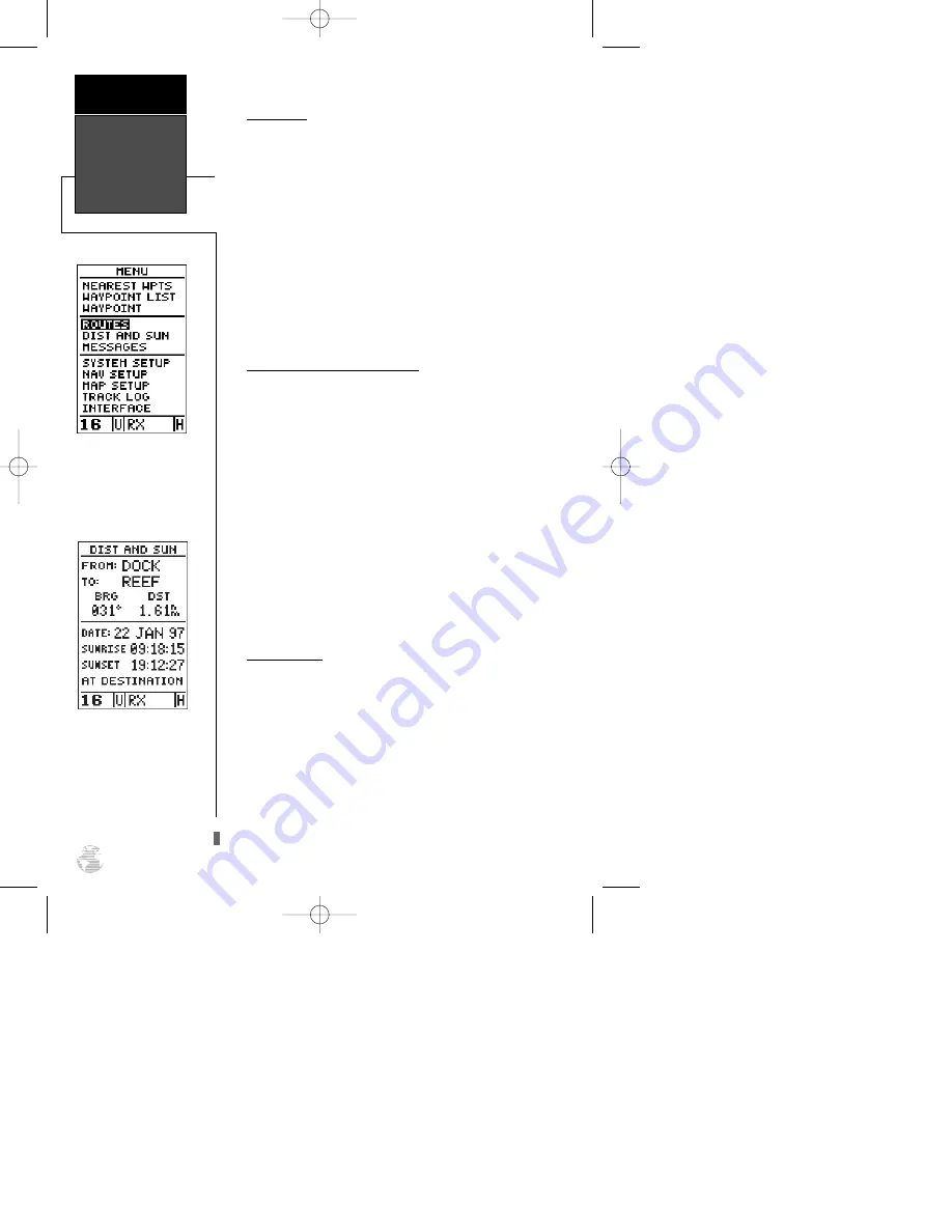
Distance and Sun Calculations

The distance and sun calculation page will give you

the distance and bearing between any two waypoints and
will calculate the sunrise and sunset (in local time) at a
destination waypoint for a particular date.

To perform a distance and sun calculation:

1. Highlight the ‘from’ field and enter the desired way-

point. Press 

E

to move to the next field.

2. Highlight the ‘to’ field and enter the destination way-

point. Press 

E

to calculate the range and bearing

to the destination waypoint.

3. Highlight the ‘date’ field and enter the date for your

destination. Press 

E

to display the sun 

information.

Message Page

The message page displays all current messages in the

GPSCOM 170. There are two types of messages: tempo-
rary alerts (eg., approaching a waypoint) and condition
alerts (eg., battery power is low). All messages are initial-
ly indicated by a flashing on-screen box. After a tempo-
rary alert has been viewed, it is cleared. Condition alerts
are displayed on the message page until the condition is
resolved. See Appendix E for a complete list of messages.

To view the message page:

1. Highlight the ‘MESSAGES’ field and press 

E

.

Menu Page

Reference

56

Menu Page

To select a submenu, use the
UP and DOWN keys to
highlight a menu option and
press ENTER.

Dis/Sun Calculation

The unit will calculate the
sunrise and sunset times of
any stored waypoint or your
present position. To calcu-
late, enter the date and year
and press ENTER.

170 manual pages rev D  9/21/98 9:23 AM  Page 56

Summary of Contents for GPSCOM 170

Page 1: ...G P S C O M 1 7 0 O w n e r s M a n u a l R e f e r e n c e 170 cover 9 21 98 9 31 AM Page 1 ...

Page 2: ...ic or manual including photocopying and recording for any purpose without the expressed written permission of GARMIN Information in this document is subject to change without notice GARMIN reserves the right to change or improve its products and to make changes in the content without obligation to notify any person or organization of such changes or improvements GARMIN AutoLocate AutoStore AutoZoo...

Page 3: ... or desired contact the FCC at 1 800 322 1117 to request form 506 Application for Ship Radio Station License The FCC also has a fax on demand service to provide forms by fax at 1 202 418 0177 The GPSCOM 170 owner accepts all responsibility for obtaining the proper licensing before using the transmitter ii WARNING This transmitter will operate on channels frequen cies that have restricted use in th...

Page 4: ...you are missing any parts please contact your dealer immediately GPSCOM 170 OWNER S MANUAL GPSCOM 170 Unit Flex Whip Com Antenna Quick Reference Card Owner s Manual Trickle Charger AC Adapter Belt Clip Carrying Case Wrist Strap Packing List INTRODUCTION iii 170 manual pages rev D 9 21 98 9 23 AM Page iii ...

Page 5: ...ssary FCC standards This equipment generates uses and can radiate radio frequency energy and if not installed and used in accordance with the instruc tions may cause harmful interference to radio communications However there is no guarantee that interference will not occur in a particular installation If this equipment does cause harmful interference to other equipment which can be determined by t...

Page 6: ...sing the VHF Transceiver 29 38 GOTO MOB and TracBack Navigation 39 41 Route Navigation 42 47 Navigation Guidance Pages 48 55 Menu Page 56 System Setup 57 63 Appendix A Initializing the Receiver 64 66 Appendix B Accessories and Installation 67 69 Appendix C VHF Channel List 70 71 Appendix D Specifications 72 73 Appendix E Messages 74 75 Appendix F Map Datums 76 77 Appendix G Time Offset Chart 78 Ap...

Page 7: ...ocated on the front of the unit provides control of the navigation and communica tion functions The 16 9 key allows for one button selection of channel 16 or 9 Knobs for controlling squelch power and volume are located on top of the unit The micro phone is located in the lower left speaker area Front View Internal GPS Antenna Squelch Control Volume Control BNC Antenna Connector Top View Unit Descr...

Page 8: ...nd push to talk PTT switch are located on the left side of the unit The connector for the external GPS antenna and power data ext speaker ext mic cable are located on the right side A removable Ni Cad battery pack powers the unit and attaches to the back See Appendix B for instructions on installing and removing the battery pack Side Views Removable Battery Pack Unit Description introduction 3 H L...

Page 9: ... and restores a data field s previous value K The PAGE key scrolls through the main data pages in sequence and returns the display from a submenu page to a main page It also displays the message screen when a message alert appears The GOTO key displays the GOTO waypoint page allowing you to select the destination waypoint B Use the LEFT and RIGHT arrow keys to move the selected character field and...

Page 10: ...tton illuminates the arrow keypad and LCD Screen through four levels of backlighting three levels of brightness and off C Keys and Controls introduction 5 T The DUAL TRI key activates dual and tri watch monitoring N The 16 9 key selects channel 16 or 9 for immediate use M The MEM key accesses the memory setup page which enables you to program channels into memory U D CHAN The CHANNEL SELECTION arr...

Page 11: ...r graph and a satellite sky view in the center of the page The accuracy of your position is shown in the upper right hand side of the page The satellite sky view and signal strength bars give you an indication of what satellites are visible to the receiver and whether they are being tracked Satellites labeled with numbers and letters are placed on the page indicating their position in the sky The ...

Page 12: ...ays from left to right the current channel band of operation operating mode and output power level The VHF status field elements are discussed in detail in the reference section The graphic compass display is designed to show your cur rent track and does not serve as a true magnetic compass while you re standing still Position Page Getting Started 7 Graphic Compass Tape Current Track Time of Day S...

Page 13: ...e right arrow key once to move the character highlight to the next character space 5 Repeat steps 3 and 4 until the word HOME is displayed 6 Press Eto complete entry of the name 7 Press the down arrow key once to return the field high light to the SAVE field 8 Press Eto confirm that you want to save the posi tion as a waypoint named HOME The mark position page will now be replaced by the position ...

Page 14: ...ongi tude and approximate altitude of your position along with a resettable trip odometer are continuously dis played in the middle of the page with the time of day dis played below Now let s change the display to the moving map page and watch the track log of our walk 1 Press the Pkey to change from the position page to the map page Position and Map Pages Getting Started 9 Map Page The map page d...

Page 15: ...aypoint Once you ve stored a waypoint in memory you can use the GPSCOM 170 to guide you to it by performing a simple GOTO A GOTO is really nothing more than the receiver drawing a straight line course from your present position to the destination you ve selected To see how it works let s try navigating back to our starting position the HOME waypoint To select a GOTO destination 1 Press G 2 The Gwa...

Page 16: ...waypoint relative to the direction you are moving Your present position is represented by the diamond in the center of the course deviation scale The line down the middle of the highway represents your desired track As you navigate toward a waypoint the highway will actually move indicating the direction you re off course relative to the position square on the CDI scale To stay on course simply st...

Page 17: ...e previous page There s also a compass page to helps provide better steering guidance where straight line navigation is not possible To select the compass page 1 While viewing the highway page press Etwice The compass page will now become the displayed navigation page This page provides a directional pointer to your destination by using a rotating compass display to show direction of travel It pro...

Page 18: ...rom the main GPS page sequence is the menu page which provides access to the GPSCOM 170 s waypoint management route track log and setup features The 11 submenus are divid ed into categories by function To select a submenu from the menu page 1 Press Por Quntil the menu page appears 2 Use the arrow keypad to highlight the submenu you want to view 3 Press Eto access the submenu You ve now gone throug...

Page 19: ...Pages To move back and forth between the GPS and VHF pages press C There are three com VHF pages in a continuous loop channel definition com setup and memory bank Press C to exit the GPS pages and enter the com pages Try scrolling through the com pages by pressing P You can also scroll in the opposite direction or return to a previous page by pressing Q The function of each of the com pages is dis...

Page 20: ...na The GPSCOM 170 will not transmit using external power without the battery pack Make sure the battery pack is installed If the PTT button is held in for more than 35 sec onds the transmitter will automatically shut off The message Stuck PTT will also be displayed on the message page The GPSCOM 170 gives you the option of trans mitting using 1 watt or 5 watts of power Transmitting at 1 watt power...

Page 21: ...ency communications Before making contact with another vessel refer to the RTCM marine radio user s guide to select an appropriate channel for communications after ini tial contact Selecting a Weather Channel The GPSCOM 170 receives 10 weather channels including all 7 National Weather Service channels in and around the U S and most Environment Canada Weather Radio broadcast stations To select a we...

Page 22: ...ce or the PTT button once Congratulations You ve just completed the getting started tour You now know enough about the GPSCOM 170 to go out and have some fun with it We strongly recommend that you read on and explore the reference section which contains a closer look at all of the exciting features of the GPSCOM 170 To turn the GPSCOM 170 off 1 Turn the VOL control counterclockwise Thank you for c...

Page 23: ...oking for a particular satellite the corresponding signal strength bar will be blank and the sky view indicator will remain highlighted in reverse video Once the receiver has found the satellite a hollow signal strength bar will appear indicating that the satel lite has been found and the receiver is collecting data from it The satellite number or letter in the sky view will also change from rever...

Page 24: ...g enough satellites for a 2D or 3D fix Not Usable the receiver is unusable possibly due to incorrect initialization or abnormal satellite condi tions Turn the unit off and back on to reset Simulator the receiver is in simulator mode EZinit Prompt The satellite status page also provides access to the EZinit prompt whenever a position fix has not been cal culated the unit must be in searching AutoLo...

Page 25: ...n on the backlight which is a very small light bulb behind the screen The bulb lights the screen display for a user defined interval the default is 15 seconds after every keystroke There are three levels of light intensity When backlighting is on a bulb icon will appear in the upper right hand corner of the display To adjust the length of time the backlighting will stay on refer to system setup in...

Page 26: ...distance travelled while navigating To reset the trip odometer 1 Highlight the TRIP field 2 Press E followed by the left arrow key 3 Press Eto finish Altitude Display When the GPSCOM 170 is acquiring satellites or navigating in the 2D mode the last known altitude will be used to compute your position If the altitude shown is off by several hundred feet you can manually enter your altitude for grea...

Page 27: ...int name To change the default position name 1 Press the up arrow key twice to move the field high light from the SAVE field to the name field 2 Press Eto begin entry of the name Pressing the left arrow key will clear any existing data 3 Use the arrow keypad to enter a value in the appropri ate character field and to move to each character position 4 Press Eto confirm the waypoint name The field h...

Page 28: ...s page can give you the closest points of safety in your area The nearest waypoints page will also let you retrieve a way point definition page or GOTO a selected waypoint right from the list To review the waypoint definition page of a highlight ed waypoint from the list 1 Press E To return to the nearest waypoint page when the DONE field is highlighted 1 Press E To GOTO a highlighted list waypoin...

Page 29: ...aypoint 2 To select a highlighted waypoint as a destination press G 3 Once the GOTO waypoint page appears press E to confirm the selected waypoint as your destination To delete all user defined waypoints 1 Use the arrow keypad to move the cursor highlight to the delete all waypoints field and press E A warning page will appear asking if you are sure you want to delete all user defined waypoints an...

Page 30: ...eld will now become highlighted with the receiv er s last known position shown if one exists 5 Press Eto begin entry of the position 6 Use the arrow keypad to enter your position and to move to each character field 7 Press Eto confirm and save your coordinates The default waypoint comment UTC date and time of creation will appear and the highlight will move to DONE 8 Press Eto return to the menu p...

Page 31: ...ence field blank to use your present position 6 Use the arrow keypad to enter the waypoint name 7 Press Eto confirm your entry 8 Enter the bearing and distance of your new waypoint from the reference waypoint Remember to use the Ekey to begin entry and confirm each field The coordinates will be calculated and saved for your new waypoint 9 Press E with the done field highlighted to return to the me...

Page 32: ...t the comment field Use the left arrow of the arrow keypad to clear the comment field 2 Press Eto begin entry of your comment 3 Enter the comment and press Eto confirm Renaming and Deleting Waypoints The rename and delete function fields are located at the bottom left of the waypoint definition page you ll need to use the arrow keypad to move the field highlight out of its standard up and down scr...

Page 33: ...nts from a waypoint field 1 Highlight the waypoint name field and press E 2 Press the left arrow key to clear the name field 3 Use the keypad to scroll through waypoints 4 If you have more than one waypoint that begins with the same letter or number you must use the right arrow key to move to the next character positions as needed Only the first character match is listed for each character set 5 O...

Page 34: ...n the opposite direction or return to a previous page by pressing Q Press P repeatedly until you access the com setup page Com Setup Page The com setup page allows you to do the following Change the mode of operation Customize the scanning setup Set the timeout feature scanning delay Select the band of operation Change the call channel Access the line of sight calculator page Com Setup Page VHF Co...

Page 35: ... select an option and press Eto confirm your choice Selecting the weather alert mode option accesses the weather alert page where you can choose to mute the weather broadcast audio The receiver will unmute and remain unmuted once a severe weather tone is received from the NWS To mute the weather broadcast audio 1 Highlight the Com Mode field and press E 2 Use the arrow keypad to select Weather Ale...

Page 36: ...ning Scanning Modes The GPSCOM 170 has two scanning modes normal and priority Normal scanning the default setting scans through all channels memory channels in sequence Channel 16 is checked in sequence as with the other channels Priority scanning scans through all channels memory channels in sequence while constantly monitoring chan nel 16 When a signal is detected on channel 16 the unit pauses o...

Page 37: ...hlight the BAND field and press E 2 Use the arrow keypad to select USA Canada or INT L and press E 3 Press Eto confirm the selection Calling Channel The calling or hailing channel is the channel used to initiate a call to another vessel typically Channel 16 or 9 You can change the call channel on the com setup page Note When the call channel is changed the new call channel becomes the second chann...

Page 38: ...ess E The top section of the line of sight calculator page displays the transmitting antenna height field and receiv ing antenna height field The bottom of the page displays the line of sight calculation field To determine an approximate line of sight distance 1 Highlight the Transmitting Antenna Height field and press E 2 Using the arrow keypad enter the known height of your antenna the default v...

Page 39: ...field and press E 2 Use the arrow keypad to select the desired bank To enter user comments 1 Highlight the comment field and press E The first character position of the comment field is highlighted Press the left arrow key on the arrow keypad to clear the field 2 Enter a character using the arrow keypad Once the desired character is selected move to the next charac ter position using the right arr...

Page 40: ... press E Individual or groups of channels within a bank cannot be copied To remove delete all channels from a memory bank 1 Highlight the CLEAR field and press E A warning page will appear asking you if you are sure you want to remove all the channels from the bank 2 Select YES and press E Memory List Editing Once a list has been entered into a bank it can be edit ed at any time To edit a list 1 U...

Page 41: ...ernational or WX for a weather channel and the LOCKOUT field Channel Definitions There is a maximum of three definition fields for each channel with the FCC s default channel usage displayed If the designated usage for a channel should ever change due to a change in regulations you can change the defi nition accordingly To change a channel definition 1 Highlight the definition field you want to ch...

Page 42: ...e and return to the previously viewed page 1 Highlight DONE and press E Channel Lockout Channel lockout allows you to bypass a channel dur ing scanning To lock a channel out 1 Highlight LOCKOUT and press E 2 Use the arrow keys to select YES 3 Press Eto confirm 4 To unlock a channel repeat the steps above except select NO in step 2 Channel Lockout Reference 37 Adding a channel to memory bank 2 from...

Page 43: ...T twice The unit will scan between chan nel 16 9 and the last selected channel stopping when traffic is detected Press T or PTT to cancel tri watch Power Override On certain channels the FCC requires the transmit ting power to be limited to and remain at one watt see Appendix C The default setting on these channels is one watt and cannot be changed There are also some one watt initial channels in ...

Page 44: ...active GOTO 1 Press G 2 Use the arrow keypad to move the field highlight to the CANCEL GOTO prompt at the bottom of the page and press E Man Overboard Function The GPSCOM 170 s man overboard function MOB lets you simultaneously mark and set a course to a posi tion for quick response to passing positions like the spot where your hat blew overboard To activate the MOB mode 1 Press Gtwice The GOTO wa...

Page 45: ... Use the arrow keypad to highlight CLEAR LOG and press E The clear log confirmation page will appear Highlight YES and press E To activate a TracBack route 1 From the map page press Eand highlight the TRACK LOG option 2 Press Eto access the track log page 3 Highlight the TRACBACK option and press E Once the TracBack function has been activated the unit will take the track log currently stored in m...

Page 46: ...sim ply draw a straight line between any point where coverage was lost and where it resumed If the changes of direction and distance of your track log are very complex 30 waypoints may not be enough to accurately mark your exact path The receiver will then assign the 30 waypoints to the most significant points of your track and simplify segments with fewer changes in direction If you want to save ...

Page 47: ...r segments called legs The waypoint you are going to in a leg is called the active to waypoint and the waypoint immediately behind you is called the active from way point The line between the active to and the active from waypoint is called the active leg Whenever you activate a route with the GPSCOM 170 it will automatically select the route leg closest to your position as the active leg As you p...

Page 48: ...the route is indicated below the waypoint list The bottom of the route definition page features sev eral function fields which let you copy clear invert or activate the displayed route Routes 1 19 are used as stor age routes with route 0 always serving as the active route you are navigating If you want to save a route currently in route 0 be sure to copy it to another open route as it will be over...

Page 49: ...anges to the active or TracBack route and want to save the route for future use To copy a route 1 Highlight the route number field and press E 2 Enter the route number to be copied and press E 3 Highlight the COPY TO field and press E 4 Scroll through the available routes and select a desti nation route number Only open routes will be available as choices Press Eto copy the route 5 Press Pto retur...

Page 50: ...u may edit during navigation and save as an entirely new route from the original You will have to copy the active route to an unused storage route to save it since new route or TracBack activation overwrites route 0 To activate a route 1 Select the route definition page and press Eto acti vate the route number field 2 Enter the route number to be activated and press E 3 Move the field highlight to...

Page 51: ...allows you to clear stop navigating or invert the active route without using the route definition page To invert a route from the active route page 1 Move the field highlight to the INVERT prompt 2 Press Eto invert the route To clear the active route from the active route page and stop route navigation 1 Select the CLEAR prompt 2 Press Eto clear the active route Editing Routes Once a route has bee...

Page 52: ... route will be overwritten by a new route activation If you add delete or change the first or last waypoint of a route the default comment first and last waypoint will automatically be updated after your changes On Route GOTOs At the beginning of this section we mentioned that the GPSCOM 170 will automatically select the route leg closest to your position as the active leg This will give you steer...

Page 53: ...The compass page is ideal for activities like trawling or entering a harbor and provides better steering guidance for slow speed e g walking travel with many directional changes Both pages provide a digital display of the bearing and distance to the destination your current speed and track over the ground and course deviation indicator CDI You can select the desired navigation page at any time To ...

Page 54: ... navigate toward a waypoint the highway will actually move indicating the direction you re off course relative to the position diamond on the CDI scale To stay on course simply steer toward the center of the highway If you do get off the desired course by more than 1 5th of the selected CDI range the exact distance you are off course will be displayed where the CDI scale set ting normally appears ...

Page 55: ...your present position while the d bar the mov ing vertical line on the scale indicates the direction and dis tance you are off the desired straight line course To stay on course steer toward the d bar until it is cen tered on the position diamond The default setting of the CDI scale is 0 25 miles with each mark representing 0 05 miles of course deviation If you do get off course by more than the s...

Page 56: ...is tance to a destination waypoint and your current track and speed over the ground The two fields at the top cor ners of the map show your bearing and distance to one of three selectable destinations an active destination way point a highlighted on screen waypoint or the panning target crosshair If you are not navigating to a waypoint or using the panning function the top data fields will not be ...

Page 57: ... for the mov ing map The distance and bearing to a destination will now be replaced by the distance and bearing from your present position to the target crosshair As you pan around the map you ll notice that the tar get crosshair will snap to on screen waypoints and high light the waypoint name Once a waypoint name is high lighted you can review its waypoint definition page or execute a GOTO funct...

Page 58: ...t crosshair as an instant GOTO destination Similar to the MOB mode this func tion will mark and instantly set a course for a new way point called MAP To GOTO the target crosshair 1 Press Gto capture the position 2 Press Eto confirm the MAP GOTO If you want to save the MAP waypoint be sure to rename it as it will be overwritten the next time a map GOTO is executed Moving Map Page Reference 53 Marki...

Page 59: ... or plotted on the map page by selecting YES or NO in the appropriate field RINGS displays the three present position range rings on the map ROUTE plots the straight leg lines between way points of an active route and displays all route waypoint names NEAREST shows the nine nearest waypoints to your present position not to the target cursor on the map NAMES displays the waypoint name for the nine ...

Page 60: ...ides good resolution with min imal screen clutter The maximum setting is 768 points Once you ve reached the maximum number of track points the older points will be lost as new points are added Note that adjusting the track points displayed will not affect whether the receiver records a track log or the ability to create a TracBack route Managing and Clearing the Track Log The rest of the track set...

Page 61: ... field 2 Highlight the to field and enter the destination way point Press Eto calculate the range and bearing to the destination waypoint 3 Highlight the date field and enter the date for your destination Press Eto display the sun information Message Page The message page displays all current messages in the GPSCOM 170 There are two types of messages tempo rary alerts eg approaching a waypoint and...

Page 62: ...ypad to select a mode and press E Date and Time Setup The date and time field is located directly below the mode field Because the time shown is UTC time you will need to enter a time offset to display the correct local time for your area To determine the time offset for your area note your position and refer to the chart in Appendix G To enter the time offset 1 Highlight the OFFSET field and pres...

Page 63: ...e 0 setting will keep back lighting on continuously Whenever backlighting is on a bulb icon will appear on the status page To set the backlight timer 1 Highlight the LIGHT field and press E 2 Use the up and down arrow keys to toggle through and select the desired setting and press E 3 To turn lighting on and off press the backlight button Tone Setting You may choose from three settings for audible...

Page 64: ...m listing in Appendix F you should only change the datum if you are using maps or charts that specify a different datum than WGS 84 To select a map datum 1 Highlight the MAP DATUM field and press E 2 Use the up and down arrow keys to toggle through and select the desired setting Confirm the setting by pressing E CDI Scale Setup The course deviation indicator CDI scale definition field lets you sel...

Page 65: ...user defined magnetic heading 1 Select the USER MAG option and press E 2 Use the up and down arrow keys to enter the degrees and direction of magnetic variation 3 Press Eto confirm the magnetic variation value Map Setup and Orientation The map setup page can be accessed from the main menu page and the moving map page See page 54 for details on the map setup and orientation TracBack Function The ne...

Page 66: ...ress E Use the up and down arrow keys to toggle through and select the desired setting and press E To select a transfer option 1 Highlight the HOST field and press E Use the up and down arrow keys to select a setting and press E To disable all interfacing capabilities select NONE NONE If you want to output NMEA data to compatible external devices without any differential input capability select NO...

Page 67: ... Select the desired transmission rate and press E When the GPSCOM 170 is receiving DGPS correc tions from the GBR 21 the beacon receiver section of the I O setup page will display the beacon frequency and signal strength as well as the distance from the transmit ter to the beacon receiver At the bottom of the beacon receiver field a status message will keep you informed of DGPS activity A tuning m...

Page 68: ...ght SYSTEM SETUP and press E 2 Highlight the MODE field and press E 3 Use the up or down arrow keys to select SIMULATOR Press Eto confirm 4 Press Eto return to the menu page Once the simulator mode has been activated use the position compass or highway page to set your speed and track You may also enter a new position if you desire only from the position page To enter track speed and position 1 Hi...

Page 69: ... itself without using its last known position you don t need to worry about what lat lon is currently displayed on the position page as the unit is not using that information to calculate your present position To power up your unit for first time use 1 Position the internal GPS antenna so it has the best pos sible view of the sky the internal patch antenna is locat ed just above the keypad marked ...

Page 70: ... you ve had the unit on in normal mode while indoors or if the antenna is shaded while acquiring satellites To initialize the receiver 1 Use the up or down arrow keys to highlight the COUNTRY option and press E 2 Use the down key to scroll through the country listings until the country where you are presently located appears 3 Use the up or down arrow key to highlight the country state region you ...

Page 71: ...gers metal sur faces or other obstructions the unit may not be receiving enough satellite signals to calculate a fix Is the right country state selected from the EZinit list Check for the correct approximate lat lon on the position page or reselect the appropriate country from the list to restart the initialization Have you moved more than 500 miles from the last calculated position with the recei...

Page 72: ...A side pocket is included for easy storage of the com antenna Belt Clip The GPSCOM 170 includes a sturdy belt clip so you can carry the unit with you wherever you go To attach the clip you will need to remove the rubber bumper from the back of the unit Attach the clip using the two screws just removed from the bumper as shown in the figure below Accessories Installation APPENDIX B 67 Belt Clip Rub...

Page 73: ...emove the Ni Cad battery pack 1 Press down on the battery pack latch pull down on the pack and remove Accessories Installation APPENDIX B 68 Battery Pack Latch Battery Pack Removal 170 manual pages rev D 9 21 98 9 23 AM Page 68 ...

Page 74: ...tery pack component failures Battery Pack Handling and Storage The Ni Cad battery supplied with the GPSCOM 170 has exposed terminals which may be shorted if not stored properly Don t place a loose battery pack on or near metal objects paper clips keys tools etc and be care ful when placing battery packs in handbags toolboxes etc Never immerse a battery pack in water If the battery pack becomes wet...

Page 75: ...50 156 500 156 550 156 600 156 650 156 700 156 750 156 800 156 850 156 900 156 900 156 950 156 950 157 000 157 050 157 050 157 100 157 100 157 150 157 150 157 200 157 250 157 300 156 350 157 400 156 025 156 075 156 075 156 125 INT 01 02 03 04 05 06 07 08 09 10 11 12 13 14 15 16 17 18 19 20 21 22 23 24 25 26 27 28 60 61 62 USA 01A 03A 05A 06 07A 08 09 10 11 12 13 14 15 16 17 18A 19A 20 21A 22A 23A ...

Page 76: ...5 161 525 156 925 161 575 156 975 161 625 157 025 161 675 157 075 161 725 157 125 161 775 157 175 161 825 161 875 161 925 161 975 162 025 157 425 INT 63 64 65 66 67 68 69 70 71 72 73 74 77 78 79 80 81 82 83 84 85 86 87 88 USA 63A 64A 65A 66A 67 68 69 70 71 72 73 74 77 78A 79A 80A 81A 82A 83A 84 85 86 87 88 88A CAN 62A 64 64A 65A 66A 67 68 69 70 71 72 73 74 77 78A 79A 80A 81A 82A 83 83A 84 85 86 87...

Page 77: ...2 Acquisition Time Approx 15 seconds warm start Approx 45 seconds cold start Approx 5 minutes AutoLocate Update Rate 1 second continuous Position Accuracy 1 5 meters 16 33 ft with DGPS corrections 15 meters 49 ft RMS Velocity Accuracy 0 1 knot RMS steady state 99 knots max Dynamics Performs to specification to 6g s Transceiver Frequency Bands All U S Canadian and International marine chan nels plu...

Page 78: ...keyed Microphone Internal electret or optional external mic headset Compliance FCC Part 87 POWER Source 1 7 2v 1800 mAh Ni Cad battery pack or 9 33 VDC external Battery Life 6 hours low and 4 hours high GPS COM GPS only 10 hours Current Consumption Standby 150 mA GPS on Com Off Receive 240 mA GPS on Com Rx Transmit 2 4 A High Power 1 3 A Low Power Based on ratio of 5 transmit 5 receive and 90 stan...

Page 79: ...ice center Poor GPS Coverage The unit cannot acquire the necessary number of satellites to compute a position Try another location with a clearer view of the sky Power Down and Re init The unit is not able to calculate a position due to abnormal satellite conditions Turn the unit off and veri fy the last position shown by other means Try the unit again later possibly in a different loca tion Read ...

Page 80: ...y transmit ting due to a stuck microphone condition Stored Data was Lost All waypoints routes time and almanac data has been lost due to battery failure or clearing the receiver s memory Transfer has been Completed The receiver is finished uploading or downloading information to the connected device Weather Alert Tone Detected The unit has detected the NOAA severe weather tone WPT Memory is Full Y...

Page 81: ...Corrego Alegr Corrego Alegre Brazil Djakarta Djakarta Batavia Sumatra Island Indonesia Dos 1968 Dos 1968 Gizo Island New Georgia Islands Easter Isld 67 Easter Island 1967 European 1950 European 1950 Austria Belgium Denmark Finland France Germany Gibraltar Greece Italy Luxembourg Netherlands Norway Portugal Spain Sweden Switzerland European 1979 European 1979 Austria Finland Netherlands Norway Spai...

Page 82: ...Scotland Shetland Isl Wales Pico De Las Nv Canary Islands Ptcairn Ast 67 Pitcairn Astro 67 Pitcairn Isl Prov S Am 56 Prov So Amricn 56 Bolivia Chile Colombia Ecuador Guyana Peru Venezuela Prov S Chln 63 Prov So Chilean 63 S Chile Puerto Rico Puerto Rico Virgin Islands Qatar National Qatar National Qatar Qornoq Qornoq South Greenland Reunion Reunion Mascarene Island Rome 1940 Rome 1940 Sardinia Isl...

Page 83: ... Zone Offset W180 0º to W172 5º 12 W172 5º to W157 5º 11 W157 5º to W142 5º 10 W142 5º to W127 5º 9 W127 5º to W112 5º 8 W112 5º to W097 5º 7 W097 5º to W082 5º 6 W082 5º to W067 5º 5 W067 5º to W052 5º 4 W052 5º to W037 5º 3 W037 5º to W022 5º 2 W022 5º to W007 5º 1 W007 5º to E007 5º 0 Longitudinal Zone Offset E007 5º to E022 5º 1 E022 5º to E037 5º 2 E037 5º to E052 5º 3 E052 5º to E067 5º 4 E0...

Page 84: ...e 62 Data Entry 8 Date and Time Setup 57 Deleting Waypoints 24 Distance and Sun Calculations 56 Dual Watch 17 E EZinit 65 Editing Waypoints 27 Editing Routes 46 Environment Canada 16 Estimated Time Enroute ETE 11 F FCC ii Flex Antenna 67 G GOTO 10 GPS Pages 13 H Highway Page 11 I Initializing the Receiver 64 Interface Setup 61 K Keys and Controls 4 M Map GOTO 53 Magnetic Heading 60 MOB 39 Managing...

Page 85: ...p 31 Scanning Waypoints 28 Screen Backlighting and Contrast 50 Selecting Channel 16 9 16 Selecting Map Scales 52 Selecting a Channel 14 Selecting a GOTO Destination 39 Selecting a Weather Channel 16 Selecting an Operating Band 32 Signal Strength Bars 18 Simulator Mode 63 Sky View 18 Specifications 72 73 Speed Track and Position 63 System Setup 57 T Time Format 50 Time Offset 67 Time Offset Chart 7...

Page 86: ...d 7 W Warranty 80 Waypoint Comments 27 Waypoint Definition Page 25 Waypoint List Page 24 Waypoint Submenus 23 Waypoints 22 Weather Alert Page 30 Welcome Page 64 Wrist Strap 67 Z Zooming and Panning 52 Index APPENDIX H 81 170 manual pages rev D 9 21 98 9 23 AM Page 81 ...

Page 87: ...ined herein are exclusive and in lieu of all other warranties expressed or implied including any liability arising under warran ty of merchantability or fitness for a particular purpose statutory or otherwise This warranty gives you specific legal rights which may vary from state to state To obtain warranty service call the GARMIN Customer Service department 913 397 8200 for a returned merchandise...

Page 88: ...RMIN CORPORATION 1200 E 151st Street Olathe KS USA 66062 GARMIN Europe Ltd Unit 5 The Quadrangle Abbey Park Industrial Estate Romsey SO51 9AQ U K Part Number 190 00093 00 Rev D 170 cover 9 21 98 9 31 AM Page 4 ...

Reviews: