GPS 155XL/GNC 300XL Installation Manual
P/N 190-00067-22 Rev E Page 3-6
3.8
RACK INSTALLATION
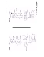
1. Figure 5-2 shows outline dimensions for the aviation rack. Install the rack in a rectangular 6.320" x
2.000" hole in the instrument panel. Exercise caution when installing the rack into the instrument panel.
The rack is designed to facilitate removal of the GPS 155XL/GNC 300XL for portable use. Deformation
of the rack may make it difficult to install and remove the GPS 155XL/GNC 300XL.
2. Install the rack in the aircraft panel using four #6-32 countersunk screws and four self-locking nuts or
other FAA-approved methods as per Advisory Circular 43.13-1A. The screws are inserted from the
inside through the holes in the sides of the rack (see Figure 5-3).
3.9
GPS 155XL/GNC 300XL INSTALLATION AND REMOVAL
1. The GPS 155XL/GNC 300XL is installed in the rack by gently sliding it straight in until it rests against
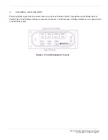
the back of the rack. A 3/32-inch hex drive tool is then inserted into the access hole at the bottom of the
unit face. Rotate the hex tool clockwise while pressing on the left side of the Bezel until the unit is
firmly seated in the rack.
2. To remove the unit from the rack, insert the hex drive tool into the access hole on the unit face and rotate
counter-clockwise until the mounting screw turns freely and the unit protrudes about 3/8 inch from the
panel.
3. Be sure not to over-tighten the unit into the rack. The application of hex drive tool torque exceeding 15
in.-lbs. can damage the locking mechanism.


