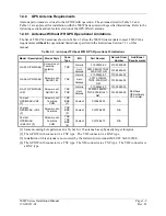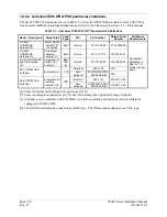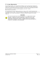
Page 1-12
500W Series Installation Manual
Rev. D
190-00357-02
1.6 Regulatory
Compliance
1.6.1
TSO and Advisory Circular References
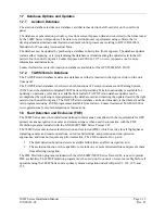
The conditions and tests required for TSO approval of this article are minimum performance standards.
It is the responsibility of those installing this article either on or within a specific type or class of aircraft
to determine that the aircraft installation conditions are within the TSO standards. TSO articles must
have separate approval for installation in an aircraft. The article may be installed only in compliance
with 14 CFR part 43 or the applicable airworthiness requirements.
For aircraft on the AML for the 400W/500W Series STC SA01933LA, the TSO design approval has
been determined to be adequate by the STC, which constitutes the separate installation design approval.
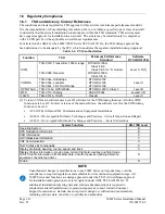
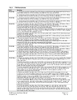
Table 1-4. TSO Authorization
Function TSO
Minimum Performance
Standard
Software
RTCA/DO-178B
TSO-C37d, Transmitter, 100nm range RTCA/DO-186A,
Class 4 & 6
Class 3 & 5 for “A” models
COM
TSO-C38d, Receiver
RTCA/DO-186A,
Class C & E
Level C, D [1]
VOR/ILS
TSO-C34e, Glideslope
TSO-C36e, Localizer
TSO-C40c, VHF Omni Range
RTCA/DO-192
RTCA/DO-195
RTCA/DO-196
Level C
GPS/WAAS
TSO-C146a, GPS/WAAS
RTCA/DO-229C, Class 3
Level B
MFD
TSO-C113, Display
SAE AS 8034
Level B,C,D
TAWS
TSO-C151b, TAWS
Class B
Level C
[1] Version 2.XX main software uses Level D software for the COM tuning function. All other COM
functions are Level C. In later versions of the main software, the software level for the COM tuning
function is Level C.
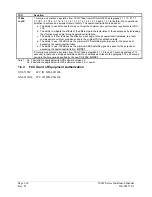
•
AC 20-67B, Airborne VHF Communications Equipment Installations
•
AC43.13-1B, Acceptable Methods, Techniques and Practices - Aircraft Inspection and Repair
•
AC43.13-2A, Acceptable Methods, Techniques and Practices - Aircraft Alterations
System Function
DO-178B Level
Operating System
B
GPS Navigation Information
B
VOR Information
C
LOC/Glideslope Information
C
VHF Communication
C
TAWS (Class B) Functionality
C
Display of altitude, heading, course, speed, and track
C
Display of other information - moving map, terrain, flight plan overlay and flight mode,
TAS/TIS traffic information, XM Weather data, data from passive lightning detection
equipment, checklist and timer
D
Terrain
D
NOTE
Unauthorized changes or modifications to any 500W Series unit product may void the
compliance to required regulations and authorization for continued equipment usage. All
500W Series unit functions are design approved under the TSO. Airworthiness approval
for installation and operational use is recognized under AML STC SA01933LA. If
additional information (drawing lists and software documentation) is required to
substantiate aircraft installation or operational approval, contact Garmin Customer
Support for assistance. Garmin does not provide design or certification documentation,
including software data, other than to certification authorities.
Summary of Contents for GNS 530W
Page 2: ...500W Series Installation Manual 190 00357 02 Rev D...
Page 130: ...Page 7 4 500W Series Installation Manual Rev D 190 00357 02 This Page Intentionally Left Blank...
Page 132: ...Page 8 2 500W Series Installation Manual Rev D 190 00357 02 This Page Intentionally Left Blank...
Page 134: ...Page A 2 500W Series Installation Manual Rev D 190 00357 02 This Page Intentionally Left Blank...
Page 136: ...Page B 2 500W Series Installation Manual Rev D 190 00357 02 This Page Intentionally Left Blank...
Page 137: ...500W Series Installation Manual Page C 1 190 00357 02 Rev D Appendix C RESERVED...
Page 138: ...Page C 2 500W Series Installation Manual Rev D 190 00357 02 This Page Intentionally Left Blank...
Page 148: ...Page E 6 500W Series Installation Manual Rev D 190 00357 02 This Page Intentionally Left Blank...
Page 150: ...Page F 2 500W Series Installation Manual Rev D 190 00357 02 This Page Intentionally Left Blank...
Page 160: ...Page G 6 500W Series Installation Manual Rev D 190 00357 02 This Page Intentionally Left Blank...
Page 162: ...Page H 2 500W Series Installation Manual Rev D 190 00357 02 This Page Intentionally Left Blank...
Page 188: ...Page H 28 500W Series Installation Manual Rev D 190 00357 02 Figure H 16 GTX 330 Interconnect...
Page 194: ...Page H 34 500W Series Installation Manual Rev D 190 00357 02 Figure H 20 RMI OBI Interconnect...
Page 198: ...Page H 38 500W Series Installation Manual Rev D 190 00357 02 Figure H 24 TAWS Interconnect...
Page 211: ...500W Series Installation Manual Page H 51 190 00357 02 Rev D Figure H 33 Switches Interconnect...
Page 215: ......
Page 216: ......


