background image

GMR Fantom

 50/120 Series

Installation Instructions

Important Safety Information

 WARNING

See the Important Safety and Product Information guide in the product box for

product warnings and other important information.
The radar transmits electromagnetic energy. Ensure that the radar is installed

according to the recommendations in these instructions and that all personnel

are clear of the path of the radar beam before transmitting. When properly

installed and operated, the use of this radar conforms to the requirements of

ANSI/IEEE C95.1-1992 Standard for Safety Levels with Respect to Human

Exposure to Radio Frequency Electromagnetic Fields.
When the radar is transmitting, do not look directly at the antenna at close

range; eyes are the most sensitive part of the body to electromagnetic energy.
When connecting the power cable, do not remove the in-line fuse holder. To

prevent the possibility of injury or product damage caused by fire or

overheating, the appropriate fuse must be in place as indicated in the product

specifications. In addition, connecting the power cable without the appropriate

fuse in place voids the product warranty.

 CAUTION

This device should be used only as a navigational aid. Do not attempt to use

the device for any purpose requiring precise measurement of direction,

distance, location, or topography.
Always wear safety goggles, ear protection, and a dust mask when drilling,

cutting, or sanding.
Opening the device may result in personal injury and/or damage to the device.

This device contains no user-serviceable parts, and should be opened only by

a Garmin

®

 authorized service technician. Any damage resulting from opening

the unit by anyone other than a Garmin authorized service technician will not

be covered by the Garmin warranty.

NOTICE

When drilling or cutting, always check what is on the opposite side of the

surface.

Registering Your Device

Help us better support you by completing our online registration today. Keep

the original sales receipt, or a photocopy, in a safe place.

1

Go to my.garmin.com/registration.

2

Sign in to your Garmin account.

Tools Needed

• #2 Phillips screwdriver
• 5 mm hex wrench
• Drill
• 15.0 mm (

19

/

32

 in.) drill bit

• 32 mm (1 

1

/

4

 in.) drill bit (optional)

• 17 mm (

21

/

32

 in.) wrench and torque wrench

• 3.31 mm² (12 AWG) copper wire to ground the radar housing and voltage

converter, if applicable (the length depends on the distance from the radar

to ground)

• Marine sealant

Mounting Considerations

When selecting a mounting location, observe these considerations.

• It is highly recommended that the device is mounted out of range of

people, with the vertical beam width above head height. To avoid exposure

to harmful radio frequency (RF) levels, the device should not be mounted

closer to people than the maximum safe distance value listed in the

product specifications.

• The device should be mounted high above the ship’s keel line with minimal

blockage of the radar beam. Obstructions may cause blind and shadow

sectors or generate false echoes. The higher the installation position, the

farther the radar can detect targets.

• The device should be mounted on a flat surface or a platform that is

parallel to the vessel's water line and is sturdy enough to support the

device's weight. The weight for each model and antenna is listed in the

product specifications.

• The device must be mounted in a location where it can be connected to

power, water ground, and the Garmin Marine Network (Wiring and

Connection Considerations, page 3).

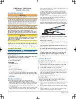
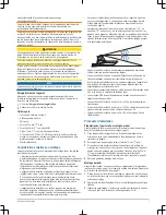
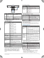
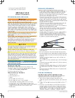
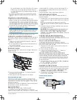
• The radar beam spreads vertically 11.5° above and 11.5° below 

À

 the

radar's radiating element. On vessels with higher bow angles at cruise

speed, the installation angle can be lowered to point the beam slightly

downward to the waterline while at rest. Shims can be used if necessary.

• The device should be mounted away from heat sources, such as smoke

stacks and lights.

• The device should be mounted at a different level than horizontal

spreaders and mast crosstrees.

• To avoid interference with a magnetic compass, the device should not be

mounted closer to a compass than the compass-safe distance value listed

in the product specifications.

• Other electronics and cables should be mounted more than 2 m (6.5 ft.)

from the radar beam path.

• GPS antennas should be either above or below the radar beam path.
• The device should be mounted at least 1 m (40 in.) from any transmitting

equipment.

• The device should be mounted at least 1 m (40 in.) away from cables

carrying radio signals such as VHF radios, cables, and antennas.

• The device should be mounted at least 2 m (6.5 ft.) away from Single Side

Band (SSB) radios.

Installation Procedures

Preparing the Radar Mounting Surface

Before you can mount the radar, you must choose a suitable mounting location

(Mounting Considerations, page 2).

1

Secure the included mounting template to the surface at the mounting

location, along the bow-stern axis, as indicated on the template.

2

Drill the mounting holes using a 15 mm (

19

/

32

 in.) drill bit.

3

If you need to run the power and network cables through the mounting

surface, select a location along the center channel indicated on the

template, drill a pass-through hole for the cables using a 32 mm (1

1

/

4

 in.)

drill bit, and route the cables through the surface (optional) (Wiring and

Connection Considerations, page 3).

4

Remove the mounting template from the surface.

Mounting the Radar

Before you can mount the radar, you must select a mounting location

(Mounting Considerations, page 2) and prepare the mounting surface

(Preparing the Radar Mounting Surface, page 2).

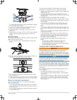
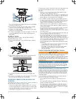
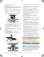
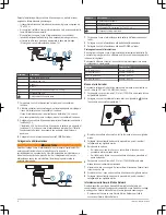
1

Place the radar onto the mounting surface, aligning the holes on the base

of the radar with the holes you drilled when preparing the mounting

surface.

2

Apply the included Petrolatum Primer to the threads of the four threaded

rods.

3

Insert the threaded rods 

À

 through the mounting surface and into the

radar base, and tighten them using a  5 mm hex wrench.

2

Installation Instructions

Summary of Contents for GMR FANTOM 50 Series

Page 1: ...7 Installationsinstruktioner 42 Garmin and the Garmin logo are trademarks of Garmin Ltd or its subsidiaries registered in the USA and other countries GMR Fantom and MotionScope are trademarks of Garmin Ltd or its subsidiaries These trademarks may not be used without the express permission of Garmin El número de registro COFETEL IFETEL puede ser revisado en el manual a través de la siguiente página...

Page 2: ...ed high above the ship s keel line with minimal blockage of the radar beam Obstructions may cause blind and shadow sectors or generate false echoes The higher the installation position the farther the radar can detect targets The device should be mounted on a flat surface or a platform that is parallel to the vessel s water line and is sturdy enough to support the device s weight The weight for ea...

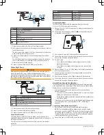
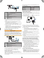
Page 3: ...cation not the negative terminal of the battery Grounding the Radar page 4 To ensure safety appropriate tie wraps fasteners and sealant should be used to secure the cable along the route and through any bulkheads or the deck You should not run cables near moving objects and high heat sources or through doorways and bilges To avoid interference with other equipment you should not run network and po...

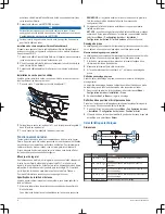
Page 4: ...opper wire not included 1 Route a 3 31 mm 12 AWG copper wire to a water ground location and to the radar pedestal 2 Connect the wire to the ground connector on the pedestal using the pre installed crimp connector À 3 Coat the ground screw and crimp connector with marine sealant 4 Connect the other end of the wire to the water ground location on the boat and coat the connection with marine sealant ...

Page 5: ...enna selection prompt appears on the connected chartplotters NOTE If the entire system is being turned on for the first time the antenna selection screen is part of the initial setup process 2 Select the installed antenna size for each open array radar installed on the boat TIP If you need to specify a different antenna size while viewing the radar screen for the radar you want to change select Me...

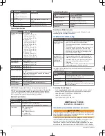
Page 6: ...this product go to developer garmin com open source linux Installation Troubleshooting Symptom Possible Causes The radar does not turn on The status LED is not on The power cable may not be connected correctly to the device or to the battery Check all connections The inline fuse may have blown Check the fuse and replace it if necessary The wire gauge used to extend the power cable may be too small...

Page 7: ... L appareil doit être installé sur une surface plane ou une plate forme parallèle à la ligne de flottaison du navire suffisamment résistante pour accueillir le poids de l appareil Le poids de chaque modèle et antenne est répertorié dans les caractéristiques techniques du produit Vous devez installer l appareil dans un endroit où il peut être branché à une source d alimentation à une prise de masse...

Page 8: ...c d étanchéité appropriés pour positionner correctement le câble tout au long de son cheminement et s il doit traverser une cloison ou le pont Vous ne devez pas acheminer les câbles à proximité d objets mobiles et de sources de chaleur par des portes ou à fond de cale Pour éviter les interférences avec d autres appareils évitez d installer les câbles d alimentation et réseau à proximité ou parallè...

Page 9: ...façon appropriée à la masse à l aide d un fil en cuivre de 3 31 mm 12 AWG non fourni 1 Acheminez un fil en cuivre de 3 31 mm 12 AWG à une prise de masse et jusqu au piédestal du radar 2 Connectez le fil au connecteur de masse situé sur le piédestal à l aide du manchon pré installéÀ 3 Enduisez la vis de masse et le manchon avec du mastic d étanchéité 4 Connectez l autre extrémité du fil à l emplace...

Page 10: ... l antenne 1 Allumez le radar et tous les périphériques connectés au réseau Garmin Marine Network Vous êtes invité à sélectionner votre antenne sur les traceurs connectés REMARQUE si le système entier est mis sous tension pour la première fois l écran de sélection d antenne fait partie du processus de configuration initial 2 Sélectionnez la taille de l antenne installée pour chaque radar poutre in...

Page 11: ...enne de 1 8 m 6 pi 1 25 degré Lobes secondaires horizontaux 23 dB 10 degrés dans le faisceau principal 30 dB 10 degrés hors du faisceau principal Largeur de faisceau vertical 22 degrés Polarisation Horizontale Licence logicielle Open Source Pour consulter la ou les licences logicielles Open Source utilisées pour ce produit rendez vous sur la page developer garmin com open source linux Installation...

Page 12: ...ino Informazioni sull installazione Scegliere la posizione di montaggio tenendo presente quanto segue Si raccomanda di installare l antenna in una posizione di sicurezza per le persone ampiezza verticale del raggio più alta della testa Per evitare esposizione a livelli dannosi di radiofrequenza RF non installare il dispositivo più vicino alle persone rispetto al valore di distanza di sicurezza mas...

Page 13: ... possibile tagliare l occhiello per consentire il passaggio di più cavi attraverso lo stesso foro L occhiello opzionale NON assicura una chiusura impermeabile Applicare del sigillante marino sull occhiello dopo aver passato i cavi per garantire una tenuta stagna Durante l installazione dei cavi è necessario considerare quanto segue Si sconsiglia di tagliare il cavo Garmin Marine Network ma se è ne...

Page 14: ...o della massa idrica 1 Far passare il cavo di alimentazione sulla batteria dell imbarcazione e sul radar 2 Collegare il cavo di alimentazione alla batteria dell imbarcazione 3 Collegare il cavo di alimentazione alla porta POWER sul radar Prolunga del cavo di alimentazione Si consiglia di collegare il cavo di alimentazione direttamente alla batteria Se è necessario prolungare il cavo utilizzare un ...

Page 15: ...tivo Android o Apple compatibile Se il chartplotter non è dotato della tecnologia Wi Fi è necessario aggiornare il software utilizzando una scheda di memoria e un computer Windows Per ulteriori informazioni visitare il sito Web support garmin com Specifica delle dimensioni dell antenna Prima di poter utilizzare il radar sul sistema è necessario specificare le dimensioni dell antenna 1 Accendere il...

Page 16: ...azioni in radiofrequenza stabiliti per le persone e ambienti non controllati Specifiche elettriche Specifica Valore Tensione operativa Da 10 a 32 V cc Fusibile Cavo di alimentazione del radar 15 A piatto Cavo del convertitore di tensione se applicabile 30 A piatto Tensione in ingresso GMR Fantom 54 e 56 Tipico 65 W Massima 170 W GMR Fantom 124 e 126 Tipica 80 W Massima 185 W Caratteristiche tecnic...

Page 17: ...rbessern und füllen Sie die Online Registrierung noch heute aus Bewahren Sie die Originalquittung oder eine Kopie an einem sicheren Ort auf 1 Rufen Sie my garmin com registration auf 2 Melden Sie sich bei Ihrem Garmin Konto an Erforderliches Werkzeug Kreuzschlitzschraubendreher Nr 2 Inbusschlüssel 5 mm Bohrmaschine 15 mm Bohrer 19 32 Zoll 32 mm Bohrer 1 1 4 Zoll optional Schraubenschlüssel und Dre...

Page 18: ...tzabdeckung À vom Hohlleiter oben auf dem Standfuß 2 Richten Sie den Hohlleiter am Standfuß Á auf die Buchse unten an der Antenne  aus und schieben Sie die Antenne auf den Standfuß 3 Befestigen Sie die Antenne am Standfuß indem Sie die unverlierbaren Sechskantschrauben unter dem Antennenarm anziehen 4 Ziehen Sie die Sechskantschrauben mit einem Drehmoment von 7 9 Nm 6 lbf ft an um die Antenne am ...

Page 19: ... zum Radargerät und zum Spannungswandler 2 Verbinden Sie das Netzkabel mithilfe von Quetschverbindern und Schrumpfschläuchen mit dem Spannungswandler Im Netzkabel des Radargeräts ist eine Sicherung mit 15 A enthalten die beim Verbinden mit dem Spannungswandler nicht entfernt werden sollte 3 Verbinden Sie den Spannungswandler über die mitgelieferte Sicherung mit 30 A mit der Bootsbatterie Die Siche...

Page 20: ...zwerkerweiterung zu verbinden 1 Verbinden Sie das Garmin Marinenetzwerkkabel mit dem Gerät und führen Sie es zum Kartenplotter oder zur Erweiterung 2 Falls es noch nicht vorinstalliert ist verbinden Sie das mitgelieferte Adapterkabel mit dem Ende des Garmin Marinenetzwerk 3 Verbinden Sie das Adapterkabel mit dem Kartenplotter oder mit der Erweiterung Montieren der Kabelabdeckung Sie müssen das Rad...

Page 21: ...m 54 100 W m2 1 75 m 5 7 Fuß 50 W m2 2 45 m 8 Fuß 10 W m2 5 40 m 17 7 Fuß GMR Fantom 56 100 W m2 2 15 m 7 1 Fuß 50 W m2 3 05 m 10 Fuß 10 W m2 6 80 m 22 3 Fuß GMR Fantom 124 100 W m2 2 65 m 8 7 Fuß 50 W m2 3 75 m 12 3 Fuß 10 W m2 8 40 m 27 6 Fuß GMR Fantom 126 100 W m2 3 35 m 11 Fuß 50 W m2 4 75 m 15 6 Fuß 10 W m2 10 55 m 34 6 Fuß Sicherheitsabstand zum Kompass 300 mm 11 8 Zoll Gewicht des Standfuß...

Page 22: ...r siempre que se instale y se maneje de forma adecuada cumple los requisitos de la norma ANSI IEEE C95 1 1992 sobre niveles de seguridad relativos a la exposición de seres humanos a campos electromagnéticos de radiofrecuencia Cuando la antena de radar esté transmitiendo no mires directamente a la antena desde una distancia próxima ya que los ojos son la parte del cuerpo más sensible a la energía e...

Page 23: ... 32 mm 11 4 in y pasa los cables por la superficie opcional Especificaciones sobre el cableado y las conexiones página 23 4 Retira la plantilla de montaje de la superficie Montar el radar Antes de montar el radar debes seleccionar una ubicación de montaje Especificaciones de montaje página 22 y preparar la superficie de montaje Preparar la superficie de montaje del radar página 23 1 Coloca el rada...

Page 24: ...taje para proporcionar la alimentación correcta al dispositivo Si el modelo se suministra con un conversor de voltaje se debe instalar para que el radar funcione Si el modelo no se suministra con un conversor de voltaje conecta el cable de alimentación directamente a la batería de la embarcación Conexión a la alimentación página 24 Al instalar el conversor de voltaje para un modelo de radar compat...

Page 25: ...ierta en la carcasa del radar puedes adquirir un cable de red Garmin con un conector recto en tu distribuidor de Garmin 2 Conecta el cable al puerto NETWORK del radar AVISO Mantén la precaución al conectar el cable al radar Si intentas conectar el cable en ángulo podrías dañar los contactos del puerto NETWORK 3 Gira el anillo del cable hacia la derecha para fijar el cable al radar Instalar un cabl...

Page 26: ...hasta la parte posterior del pedestal Á 234 7 mm 91 4 in Centro de rotación hasta la parte delantera del pedestal  86 mm 325 64 in Centro de rotación hasta los orificios de montaje posteriores à 114 mm 41 2 in Centro de rotación hasta los orificios de montaje delanteros Ä 200 mm 77 8 in Distancia entre los orificios de montaje Elemento Medida Descripción À Modelos de 4 ft 132 8 cm 4 ft 45 16 in M...

Page 27: ...mación como manuales de producto preguntas frecuentes vídeos y atención al cliente En Estados Unidos llama al 913 397 8200 o al 1 800 800 1020 En el Reino Unido llama al 0808 238 0000 En Europa llama al 44 0 870 850 1241 GMR Fantom 50 120 serien Installationsvejledning Vigtige sikkerhedsoplysninger ADVARSEL Se guiden Vigtige produkt og sikkerhedsinformationer i æsken med produktet for at se produk...

Page 28: ...eringsoverfladen skal du vælge et sted langs den centrale kanal som er angivet på skabelonen bore et gennemgangshul til kablerne med et 32 mm 11 4 tomme borehoved og føre kablerne gennem overfladen valgfrit Overvejelser om ledningsføring og tilslutning side 28 4 Fjern monteringsskabelonen fra overfladen Montering af radaren Før du kan montere radaren skal du vælge et monteringssted Overvejelser om...

Page 29: ...eller forhindre at den kan tændes Visse radarmodeller kræver en spændingsomformer til korrekt strømtilførsel til enhed Hvis der følger en spændingsomformer med din model skal den installeres for at din radar kan fungere Hvis der ikke følger en spændingsomformer med din model skal du tilslutte strømkablet direkte til bådens batteri Tilslutning af strøm side 29 Når du installerer spændingsomformeren...

Page 30: ...porten NETWORK Netværk på radaren BEMÆRK Vær forsigtig når du tilslutter kablet til radaren Hvis du forsøger at tilslutte kablet i en vinkel kan du beskadige benene på porten NETWORK Netværk 3 Drej ringen på kablet med uret for at fastgøre kablet til radaren Installation af et Garmin Marine Network adapterkabel Om nødvendigt kan du bruge det medfølgende Garmin Marine Network adapterkabel til at ti...

Page 31: ... Beskrivelse À 4 fods modeller 132 8 cm 4 fod 45 16 tommer 6 fods modeller 193 8 cm 6 fod 45 16 tommer Antennelængde Á 40 3 cm 157 8 tommer Base på soklen til toppen af antennen  28 6 cm 111 4 tommer Soklens bredde ved basen à 36 4 cm 145 16 tommer Soklens bredde i midten Fysiske specifikationer Specifikation Mål Minimal sikker betje ningsafstand GMR Fantom 54 100 W m2 1 75 m 5 7 fod 50 W m2 2 45...

Page 32: ...ensível do corpo à energia eletromagnética Ao conectar o cabo de força não remova o porta fusíveis em linha Para impedir a possibilidade de ferimentos ou danos ao produto causados por incêndio ou superaquecimento o fusível apropriado deverá estar no local conforme indicado nas especificações do produto Além disso conectar o cabo de força sem o fusível apropriado anula a garantia do produto CUIDADO...

Page 33: ...dar selecione um local para a montagem Considerações sobre montagem página 32 e prepare a superfície de montagem Preparando a superfície de montagem do radar página 33 1 Posicione o radar na superfície de montagem alinhando os furos na base do radar com os furos que você fez ao preparar a superfície de instalação 2 Aplique o Petrolatum Primer incluso as roscas nas quatro hastes roscadas 3 Insira a...

Page 34: ...a ligado adequadamente Se o seu modelo foi enviado com um conversor de tensão ele deve ser instalado para que seu radar funcione Se o seu modelo não foi enviado com um conversor de tensão conecte o cabo de alimentação diretamente à bateria da embarcação Estabelecendo conexão com a alimentação página 34 Ao instalar o conversor de tensão para um modelo de radar aplicável observe as seguintes conside...

Page 35: ...ector diretamente com o seu revendedor Garmin 2 Conecte o cabo na porta NETWORK do radar AVISO Tenha cuidado a conectar o cabo ao radar Se você tentar conectar o cabo em ângulo pode danificar os pinos na porta NETWORK 3 Gire o anel no cabo no sentido horário para prender o cabo no radar Instalar um cabo adaptador do Garmin Marine Network Se necessário você pode usar o cabo adaptador do Garmin Mari...

Page 36: ...os de montagem Item Medidas Descrição À Modelos de 1 22 m 4 pés 132 8 cm 4 pés 45 16 pol Modelos de 1 83 m 6 pés 193 8 cm 6 pés 45 16 pol Comprimento da antena Á 40 3 cm 157 8 pol Base do pedestal na parte superior da antena  28 6 cm 111 4 pol Largura do pedestal na base à 36 4 cm 145 16 pol Largura do pedestal no centro Especificações físicas Especificação Medidas Distância operacional de segura...

Page 37: ...kes riktig oppfyller bruken av denne radaren kravene i ANSI IEEE C95 1 1992 Standard for Safety Levels with Respect to Human Exposure to Radio Frequency Electromagnetic Fields Ikke se direkte på radaren på nært hold når radaren sender signaler øynene er den delen av kroppen som er mest følsom for elektromagnetisk energi Ikke fjern den innebygde sikringsholderen når du kobler til strømkabelen Rikti...

Page 38: ...nteringsoverflaten Klargjøre monteringsoverflaten for radaren side 38 1 Plasser radaren på monteringsoverflaten og pass på at hullene på radarens sokkel passer overens med hullene du drillet da du klargjorde monteringsoverflaten 2 Bruk den medfølgende Petrolatum Primer på gjengene på de fire stengene med gjenger 3 Sett inn stengene med gjenger À gjennom monteringsoverflaten og inn i radarens sokke...

Page 39: ...dellen må den være montert for at radaren skal fungere Hvis det ikke fulgte en spenningsomformer med modellen kobler du strømkabelen direkte til båtbatteriet Koble til strøm side 39 Tenk over følgende hvis du monterer en spenningsomformer Spenningsomformeren krever en inngangsspenning på 10 til 32 VDC Det anbefales at du monterer spenningsomformeren så nær strømkilden som mulig Det anbefales at du...

Page 40: ...ler GMS 10 nettverksboksen 1 Koble Garmin Marine Network kabelen til enheten og før den til kartplotteren eller nettverksboksen 2 Hvis den medfølgende adapteren ikke har blitt montert på forhånd kobler du den til i enden av Garmin Marine Network kabelen 3 Koble adapterkabelen til en kartplotter eller en nettverksboks Installere kabeldekselet Du må montere radaren trekke alle kablene og koble dem t...

Page 41: ...fot 50 W m2 3 75 m 12 3 fot 10 W m2 8 40 m 27 6 fot GMR Fantom 126 100 W m2 3 35 m 11 fot 50 W m2 4 75 m 15 6 fot 10 W m2 10 55 m 34 6 fot Trygg avstand fra et kompass 300 mm 11 8 tommer Sokkelens vekt 15 8 kg 34 8 lb Antennens vekt 4 fots antenne 5 2 kg 11 4 pund 6 fots antenne 7 3 kg 16 0 pund Lengde på strømkabel 15 m 49 fot 3 tommer Lengde på nettverkskabel 15 m 49 fot 3 tommer Antennerotasjon...

Page 42: ...ler inte garantin om du ansluter strömkabeln utan rätt säkring OBSERVERA Den här enheten bör endast användas som ett navigationshjälpmedel Försök inte att använda enheten för något ändamål där exakt mätning av riktning avstånd plats eller topografi krävs Använd alltid skyddsglasögon hörselskydd och andningsskydd när du borrar skär eller slipar Att öppna enheten kan resultera i personskador och ell...

Page 43: ...iedestalen ordentligt Montera radarn sidan 43 1 Ta bort skyddshöljet À från vågledaren på ovansidan av piedestalen 2 Justera vågledaren på piedestalen Á med uttaget längst ned på antennen  och skjut på antennen på piedestalen 3 Sätt fast antennen på piedestalen genom att dra åt sexkantsbultarna under antennens arm 4 Dra åt sexkantsbultarna till ett vridmoment på 7 9 Nm 6 fotpund för att fästa ant...

Page 44: ...r en säkring på 15 A som inte ska tas bort vid anslutning till spänningsomvandlaren 3 Anslut spänningsomvandlaren till båtbatteriet med den medföljande säkringen på 30 A Säkringen på 30 A mellan spänningsomvandlaren och batteriet ska användas utöver den säkring på 15 A som ingår i radarns strömkabel Båda säkringarna måste sitta på plats för att radarn ska fungera på rätt sätt 4 Anslut strömkabeln ...

Page 45: ...på piedestalen 3 Fäst kabelskyddet på piedestalen med de medföljande skruvarna Använda radarn Alla funktioner för den här radarn styrs med din Garmin plotter Användningsinstruktioner finns i avsnittet Radar i användarhandboken till plottern Om du vill hämta den senaste handboken går du till www garmin com manuals Om du har fler än en radar på din båt måste du visa radarskärmen för den radar som du...

Page 46: ...en Vid en sådan konfiguration uppfylls de angivna begränsningarna för exponering av radiofrekvensstrålning i befolkad icke kontrollerbar miljö Elektriska specifikationer Specifikation Mått Ingående spänning Från 10 till 32 V likström Säkring Radarns strömkabel 15 A knivsäkring Spänningsomvandlare om tillämpligt 30 A knivsäkring Spänningsmatning GMR Fantom 54 och 56 Normal 65 W Max 170 W GMR Fantom...

Page 47: ...ogramvara uppdateras Blinkande röd Radarn har påträffat ett fel Kontakta Garmin produktsup port om du behöver hjälp Kontakta Garmin support Hjälp och information finns på support garmin com till exempel produkthandböcker vanliga frågor videor och kundsupport I USA ringer du 913 397 8200 eller 1 800 800 1020 I Storbritannien ringer du 0808 238 0000 I Europa ringer du 44 0 870 850 1241 Installations...

Page 48: ... 2018 Garmin Ltd or its subsidiaries support garmin com ...

Reviews: