190-01717-B1
G500/G600 TXi Part 23 AML STC Maintenance Manual
Rev. 1
Page 3-4
3.4 Visual Inspection
Operation of the G500/G600 TXi system is not permitted unless an inspection, as described in this section,
has been completed within the preceding 12 calendar months. Conduct the following visual inspection of
the G500/G600 TXi system LRUs and associated wiring harnesses to ensure installation integrity:
WARNING
Ensure the GBB 54 vent tube is not pointed towards personnel or equipment before blowing
shop air through the tube. Any obstructions in the tube will be ejected at high speed and can
cause serious injury or property damage.
1. Inspect all units for security of attachment, including visual inspection of brackets and other
supporting structure attaching all units to the airframe.
2. Inspect all switches, annunciators, knobs and buttons for legibility.
3. Visually inspect each unit’s wiring (including electrical bonding straps), overbraid, and connectors
for chafing, deterioration, damage or wear.
4. Visually check for any signs of corrosion.
5. Visually inspect the GBB 54 vent tube and connectors for damage/corrosion and ensure there are
no obstructions in the vent tube. The vent tube can be checked for obstructions by disconnecting
the vent tube from the GBB 54 and blowing shop air through the tube from the battery connector
side to the exterior of the aircraft.
3.4.1
Aluminum Foil Tape (non-metallic aircraft only)
Any aluminum foil tape used in the G500/G600 TXi installation for grounding of a GSU 75/75B, GDC 72,
GRS 79, GAD 43/43e, or GEA 110 (see Appendix A of this document) must be inspected every 12
calendar months.
The inspection must verify that the foil tape is not torn, damaged, or showing signs of corrosion. If any of
these conditions is found, the tape must be replaced in accordance with Section 4 of the G500/G600 TXi
Part 23 AML STC Installation Manual.
3.5 Electrical Bonding Check
G500/G600 TXi LRU electrical bonding must be checked every 2000 flight hours or ten (10) years,
whichever occurs first. During the check, any cables normally attached to the LRU must be disconnected
from the LRU. Resistance must be measured from a bare metal portion of the LRU to an airframe
grounding location. The airframe grounding location should be as close to the LRU as possible unless
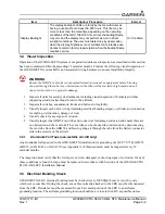
Display Backlight
The display backlight LEDs are rated by the manufacturer as
having a usable life of at least 36,000 hours. This life may be
more or less than the rated time depending on the operating
conditions of the GDU 1060/700. Over time the backlight lamp
may dim and the display may not perform as well in direct
sunlight conditions. The user must determine by observation
when the display brightness is not suitable for its intended use.
Contact a Garmin factory repair station when the backlight lamp
requires service.
On Condition
Item
Description/ Procedure
Interval

