19
Unit Operation
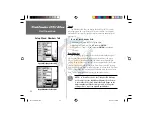
Setup Menu: Tools Tab
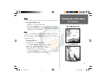
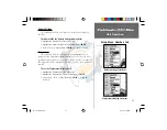
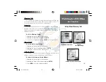
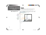
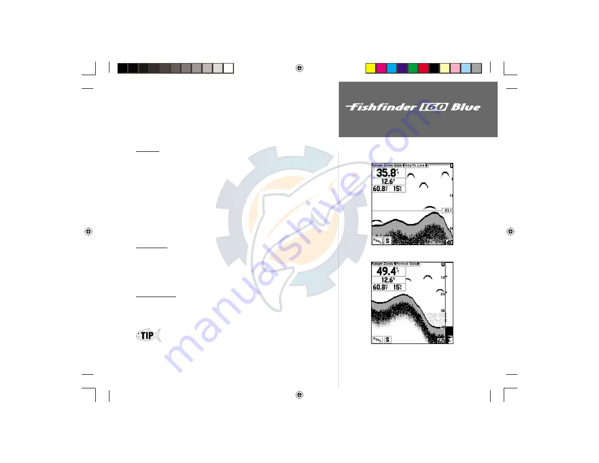
To change the Depth Line Setting:
1. Place the highlight over the ‘Depth Line’ selection on the Adjustment Bar.
2. Use the
UP
or
DOWN
Arrow to change the setting, press
ENTER
to
accept the change.
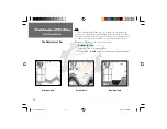
Flasher
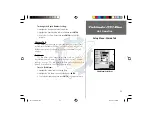
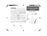
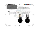
With the ‘Flasher’ tool active, a graphic Flasher representation will be
displayed on the far right side of the chart. This graphic Flasher displays
structure and bottom returns much the same as a true Flasher. You may
find this feature particularly useful when using ‘Fish Symbols.’
To Turn the Graphic Flasher on and off:
1. Highlight the ‘Tools’ tab on the Setup Menu.
2. Highlight the ‘Flasher’ selection fi eld and press
ENTER
.
3. Select ‘On’ or ‘Off’ and press
ENTER
to accept the selection.
Simulator
The ‘Simulator’ tool allows the unit to simulate the use of four different
transducer configurations: ‘Depth Only’, ‘Temp’, ‘Speed’, or ‘Temp and
Speed’. These choices allow the user to view more accurate depictions of
actual unit operation. For details on using the simulator, see page 35.
Noise Reject
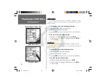
The ‘Noise Reject’ tool helps filter unwanted noise from the chart. The
‘Noise Reject’ tool can be turned ‘Off,’ set for ‘Auto’ (automatic) adjustment
or set for ‘Manual’ adjustment.
Remember when setting the Noise Reject tool, the higher the noise rejection
setting, the more likely the unit is to not show fi sh or structure.
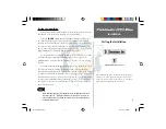
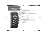
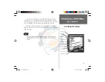
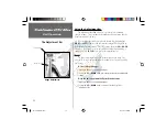
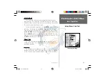
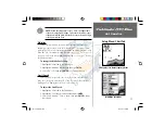
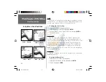
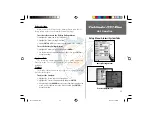
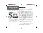
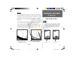
Depth Line Activated
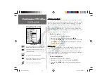
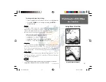
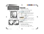
Graphic Flasher Activated
Continued on page 20
FF 160 B Rev B.indd
12/13/01, 2:50 PM
19

