background image

Screenshots

You can capture a screenshot of any screen shown on your 

chartplotter as a bitmap (.bmp) file. You can transfer the 

screenshot to your computer.

Capturing Screenshots

1

Insert a memory card into the card slot.

2

Select 

Settings

 > 

System

 > 

Display

 > 

Screenshot Capture 

On

.

3

Go to a screen you want to capture.

4

Hold 

HOME

 for at least six seconds.

Copying Screenshots to a Computer

1

Remove the memory card from the chartplotter, and insert it 

into a card reader that is attached to a computer.

2

From Windows

®

 Explorer, open the Garmin\scrn folder on the 

memory card.

3

Copy a .bmp file from the card and paste it to any location on 

the computer.

Troubleshooting

My device will not acquire GPS signals

If the device is not acquiring satellite signals, there could be a 

few causes. If the device has moved a large distance since the 

last time it has acquired satellites or has been turned off for 

longer than a few weeks or months, the device may not be able 

to acquire the satellites correctly.
• Ensure the device is using the latest software. If not, update 

the device software (

Updating the Device Software

page 40

).

• Make sure the device has a clear view of the sky so the 

antenna can receive the GPS signal. If it is mounted inside of 

a cabin, it should be close to a window so it can receive the 

GPS signal.

My device will not turn on or keeps turning off

Devices erratically turning off or not turning on could indicate an 

issue with the power supplied to the device. Check these items 

to attempt to troubleshoot the cause of the power issue.
• Make sure the power source is generating power.

You can check this several ways. For example, you can 

check whether other devices powered by the source are 

functioning.

• Check the fuse in the power cable.

The fuse should be located in a holder that is part of the red 

wire of the power cable. Check that the proper size fuse is 

installed. Refer to the label on the cable or the installation 

instructions for the exact fuse size needed. Check the fuse to 

make sure there is still a connection inside of the fuse. You 

can test the fuse using a multimeter. If the fuse is good, the 

multimeter reads 0 ohm.

• Check to make sure the device is receiving is at least 10 V, 

but 12 V is recommended.
To check the voltage, measure the female power and ground 

sockets of the power cable for DC voltage. If the voltage is 

less than 10 V, the device will not turn on.

• Make sure the device is firmly secured in the cradle. If the 

model uses a locking bracket, make sure the bracket is firmly 

snapped close. There is an audible click when the device or 

locking bracket is installed correctly. If the device is not firmly 

secured, it can lose power. The device can also fall out of the 

cradle and become damaged if it is not firmly secured.

• If the device is receiving enough power but does not turn on, 

contact Garmin product support at 

support.garmin.com

.

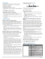
Changing the Fuse in the Power Cable

1

Open the fuse housing 

À

.

2

Twist and pull the fuse to remove it 

Á

.

3

Insert a new 3 A fast-blow fuse.

4

Close the fuse housing.

My sonar does not work

• Push the transducer cable all the way into the back of the 

device.
Even if the cable seems to be connected, you should push 

firmly so that it is fully seated.

• Press  , and ensure sonar is enabled.
• Select the correct transducer type (

Selecting the Transducer 

Type

, page 20

).

My device is not creating waypoints in the correct 

location

You can manually enter a waypoint location to transfer and 

share data from one device to the next. If you have manually 

entered a waypoint using coordinates, and the location of the 

point does not appear where the point should be, the map 

datum and position format of the device may not match the map 

datum and position format originally used to mark the waypoint.
Position format is the way in which the GPS receiver's position 

appears on the screen. This is commonly displayed as latitude/

longitude in degrees and minutes, with options for degrees, 

minutes and second, degrees only, or one of several grid 

formats.
Map datum is a math model which depicts a part of the surface 

of the earth. Latitude and longitude lines on a paper map are 

referenced to a specific map datum.

1

Find out which map datum and position format was used 

when the original waypoint was created.
If the original waypoint was taken from a map, there should 

be a legend on the map that lists the map datum and position 

format used to create that map. Most often this is found near 

the map key.

2

Select 

Settings

 > 

Units

.

3

Select the correct map datum and position format settings.

4

Create the waypoint again.

My device does not display the correct time

Time is set by GPS position and time zone setting.

1

Select 

Settings

 > 

Units

 > 

Time Zone

.

2

Ensure the device has a GPS fix.

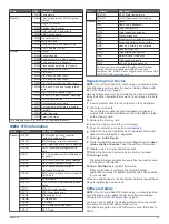
NMEA 2000 PGN Information

Type

PGN

Description

Transmit and receive 059392 ISO acknowledgment

059904 ISO request
060928 ISO address claim
126208 NMEA: Command, request, and 

acknowledge group function

126996 Product information
127250 Vessel heading
128259 Speed: Water referenced
128267 Water depth
129539 GNSS DOPs
129799 Radio frequency, mode, and power
130306 Wind data

38

Appendix

Summary of Contents for ECHOMAP 60 Series

Page 1: ...ECHOMAP 40 60 70 90SERIES Owner sManual...

Page 2: ...iveCaptain ECHOMAP FUSION Link Garmin ClearV Garmin Connect Garmin Express Garmin Quickdraw GXM HomePort OneChart and Panoptix are trademarks of Garmin Ltd or its subsidiaries These trademarks may not...

Page 3: ...ng AIS Transmission Test Alerts 8 Turning Off AIS Reception 8 Chart and 3D Chart View Settings 8 Navigation and Fishing Chart Setup 8 Chart Appearance Settings 9 Overlay Numbers Settings 9 Showing a N...

Page 4: ...Depth or Width Scale 22 Sonar Appearance Settings 22 Sonar Alarms 22 Advanced Sonar Settings 22 Transducer Installation Settings 22 Sonar Frequencies 23 Selecting Frequencies 23 Creating a Frequency P...

Page 5: ...he Presets List 32 Unlocking SiriusXM Parental Controls 32 Setting Parental Controls on SiriusXM Radio Channels 32 Changing a Parental Passcode on a SiriusXM Radio 32 Restoring Default Parental Contro...

Page 6: ...time 38 NMEA 2000 PGN Information 38 NMEA 0183 Information 39 Registering Your Device 39 Software Update 39 Loading the New Software on a Memory Card 40 Updating the Device Software 40 Garmin Support...

Page 7: ...MENU Opens a menu of options for the page when applicable Closes a menu when applicable Takes a screenshot when held ECHOMAP Plus 60 Front View Power key Automatic backlight sensor Keys microSD memor...

Page 8: ...ar with a compatible transducer transfer data such as waypoints and routes to another compatible chartplotter or a computer and use the ActiveCaptain app This device supports up to a 32 GB memory card...

Page 9: ...es connect to the Garmin Quickdraw Contours Community and update device software You can also plan your trip and view and control the ECHOMAP Plus device from the app You can connect to the ActiveCapt...

Page 10: ...update is available and you have internet access on your mobile device select OneChart My Charts 3 Select the map to update 4 Select the area to download 5 Select Download The ActiveCaptain app downl...

Page 11: ...areas NOTE Auto Guidance is available with premium charts in some areas 1 From the Navigation chart or Fishing chart select a location 2 If necessary select SELECT 3 Select Navigate To 4 Select an op...

Page 12: ...Guidance Uses specified information about your vessel and chart data to determine the best path to your destination Viewing Tide Station Information on the chart indicates a tide station You can view...

Page 13: ...ars Symbol Description Dangerous target is lost A red X indicates that the AIS transmission from the vessel is lost and the chartplotter displays a message banner asking whether the vessel should cont...

Page 14: ...ion Test Alerts To avoid a large number of test alerts and symbols in crowded areas such as marinas you can select to receive or ignore AIS test messages To test an AIS emergency device you must enabl...

Page 15: ...idance setting or the sonar shallow water alarm setting Range Rings Shows and configures the appearance of range rings which help you to visualize distances in some chart views Lane Width Specifies th...

Page 16: ...culates the laylines using manually entered windward and leeward angles Windward Angle Allows you to set a layline based on the windward sailing angle Leeward Angle Allows you to set a layline based o...

Page 17: ...elect the area to download 5 Drag the corners to change the download area 6 Select Download Area The next time you connect the ActiveCaptain app to the ECHOMAP Plus device the downloaded contours are...

Page 18: ...ge and a color for that depth range Depth Range Shading You can set color ranges on your map to show the water depths where your target fish are currently biting You can set deeper ranges to monitor h...

Page 19: ...ation or to show the location on a chart Courses CAUTION The Auto Guidance feature is based on electronic chart information That data does not ensure obstacle and bottom clearance Carefully compare th...

Page 20: ...To 4 Select an option To navigate directly to the location select Go To To create a route to the location including turns select Route To To use Auto Guidance select Auto Guidance 5 Review the course...

Page 21: ...e off course 6 Review the course indicated by the magenta line 7 Follow the magenta line along each leg in the route steering to avoid land shallow water and other obstacles 8 If you are off course fo...

Page 22: ...ent travel Auto Guidance maintains a wide clearance from obstacles in open water even if you set the Shoreline Distance setting to Near or Nearest As a result the chartplotter may not reposition the A...

Page 23: ...mended for the most efficient use of memory 1 Select Nav Info Tracks Active Track Options Record Interval Interval 2 Select an option To record the track based on a distance between points select Dist...

Page 24: ...on 2 Select the window to change 3 Select a sonar view Traditional Sonar View There are several full screen views available depending on the transducer that is connected The full screen Traditional so...

Page 25: ...D sonar views provide three dimensional views of either what is in front of or below your boat The screen updates with each sweep of the transducer To see all five Panoptix sonar views you need one tr...

Page 26: ...ers with an internal compass such as the PS21 TR transducer You can begin turning your boat before calibrating but you must fully rotate your boat 1 5 times during calibration 1 From an applicable son...

Page 27: ...Not all models support sonar recording 1 Insert a memory card into the card slot 2 From a sonar view select MENU Sonar Setup Sonar Recording Record Sonar 15 minutes of sonar recording uses approximate...

Page 28: ...ata on the screen for each column of sounder data received This is especially helpful when you are using the sounder in deep water because the sonar signal takes longer to travel to the water bottom a...

Page 29: ...quencies NOTE You cannot adjust the frequency for all sonar views and transducers You can indicate which frequencies appear on the sonar screen 1 From a sonar view select MENU Frequency 2 Select a fre...

Page 30: ...select a higher color gain value to see targets higher in the water column A higher color gain value also allow you to differentiate low intensity returns higher in the water column but this causes a...

Page 31: ...go to garmin com Autopilot Screen Actual heading Intended heading heading the autopilot is steering toward Actual heading when in standby mode Intended heading when engaged Rudder position indicator...

Page 32: ...l Racing combination screen Setting the Starting Line 1 From the starting line guidance gauge select MENU Start Line 2 Select an option To mark the port and starboard starting line marks as you sail p...

Page 33: ...MENU Autopilot Setup Wind Hold Type 2 Select Apparent or True Engaging Wind Hold Before you can enable the wind hold type you must connect a NMEA 2000 or NMEA 0183 wind sensor to the autopilot When th...

Page 34: ...t of fuel that triggers the alarm and select Done Setting the Fuel Capacity of the Vessel 1 Select Settings My Vessel Fuel Capacity 2 Enter the combined total capacity of the fuel tanks Synchronizing...

Page 35: ...station Digital Selective Calling Chartplotter and NMEA 0183 VHF Radio Functionality When your chartplotter is connected to a NMEA 0183 VHF radio these features are enabled The chartplotter can transf...

Page 36: ...transmits this request with your call Selecting a DSC Channel NOTE The selection of a DSC channel is limited to those channels that are available in all frequency bands The default channel is 72 If y...

Page 37: ...a SiriusXM Connect Vehicle Tuner see the stereo installation instructions To listen to DAB stations you must have the appropriate equipment DAB Playback page 31 For instructions on connecting a DAB ad...

Page 38: ...With the SiriusXM source selected tune to channel 1 You should be able to hear the preview channel If not check the SiriusXM Connect Tuner and antenna installation and connections and try again 2 Tune...

Page 39: ...r Turns on the simulator and allows you to set the speed and simulated location Display Settings Not all options are available on all models Select Settings System Display Backlight Sets the backlight...

Page 40: ...the water temperature measured in step 1 from the water temperature measured in step 2 This is the temperature offset Enter this value in step 5 as a positive number if the sensor connected to the ch...

Page 41: ...MEA 0183 diagnostic information Defaults Restores the NMEA 0183 settings to the original factory defaults NMEA 2000 Settings Select Settings Communications NMEA 2000 Setup Device List Displays the dev...

Page 42: ...or an Auto Guidance path with many frequent turns or at higher speeds For straighter routes or slower speeds lowering this value can improve autopilot accuracy Route Start Selects a starting point fo...

Page 43: ...on your computer and a memory card installed in the chartplotter Copy the data from HomePort to the prepared memory card For more information see the HomePort help file Backing Up Data to a Computer...

Page 44: ...uses a locking bracket make sure the bracket is firmly snapped close There is an audible click when the device or locking bracket is installed correctly If the device is not firmly secured it can los...

Page 45: ...C Digital selective calling information DSE Expanded digital selective calling HDG Heading deviation and variation HDM Heading magnetic MWD Wind direction and speed MDA Meteorological composite MWV Wi...

Page 46: ...7 Choose a location and select Save 8 Double click the downloaded file A Garmin folder containing the software update is created in the selected location A dialog box opens to assist in transferring...

Page 47: ...engine gauges 28 34 configuring 28 status alarms 28 EPIRB 8 event log 33 F factory settings 36 sonar 22 Fish Eye 3D 8 sonar cone 10 suspended targets 10 tracks 10 fishing chart 4 panning 5 setup 8 FM...

Page 48: ...l speed 21 sharing 20 SideV 18 source 20 21 surface noise 22 suspended targets 22 views 18 waypoint 20 whiteline 22 zoom 21 SOS 14 support See product support suspended targets 10 symbols 7 system inf...

Page 49: ......

Page 50: ...support garmin com October 2017 190 02242 00_0A...

Reviews: