background image

Function Test 


RTCSmp Built-In Temperature Controlled Hold-Line


Part # 4532288 Rev 3 (6/11/14) 


17 

5


Function Test 

IMPORTANT


CAUTION


When the unit is in use, the cookware will warm up the glass-top.  To 
avoid burn injuries, do not touch the glass-top. 


Remove all objects from the glass-top and verify that the glass-top is not cracked or broken. 

CAUTION


Do not continue if the glass-top is cracked or broken. Immediately 
switch off the unit and if possible and safe, disconnect it from the 
power outlet. Contact a Factory Authorized Service agency. 


Before carrying out the function test, the user must understand how to operate the unit. 


Always use a pan or a chafing dish suitable for induction cooking, having a bottom diameter of at least 
5”(12cm).  


See 

6.1 Proper Induction Serving Pan

 and 

6.2 Proper Placement of Serving Pan

.


NEVER LEAVE AN EMPTY PAN ON AN INDUCTION HOB. 

To perform a function test: 

1.


The RTCSmp HO IN 1500 unit has two heating zones. Put some water in the induction pan and place it in 
the center of a heating zone. 
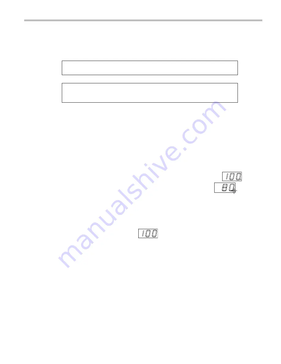
2.


Turn the control knob to select a temperature between 122-212

o

F (50-100

o

C). The digital display 

underneath the Ceran® glass shows the selected temperature followed by a dot 

. Within 2 

seconds, the display shows the actual temperature followed by a blinking dot 

. This means 

energy is being transferred to the pan and the water is heated.  

NOTE 

If you are using both heating zones at the same time, note that power is cycled from one zone 
to another. This means when the left zone is active and the dot blinks, the right zone is dormant 
and its temperature is shown without a dot, and vice versa. This is normal. 

3.


Take the pan away from the heating zone and power transmission stops. The displays shows the current 

temperature without a dot, for example 


4.


Place the pan back on the heating area and the heating process starts again; the dot blinks. 

5.


Turn the control knob to the OFF-position and the power transmission stops. If the temperature is over 
122

o

F (50

o

C), the display shows “hot”. Otherwise, the display is off. 

When the knob is in an ON-Position and the display remains off, check: 


Is the induction unit connected to the power supply? 


Is the control knob in an ON-Position? 

If the point blinks but the pan is not heated up, or the display shows the temperature without a blinking point: 


Are you using a suitable pan or dish? See section 

6.1 Proper Induction Serving Pan

.


Is the pan placed in the center of the heating area? See section 

6.2 Proper Placement of Serving Pan

For further assistance, see chapter 

10 Troubleshooting

 or call a Factory Authorized Service agency. 

Summary of Contents for IN 1500

Page 1: ...WARNING IMPROPER INSTALLATION ADJUSTMENT ALTERATION SERVICE OR MAINTENANCE CAN CAUSE PROPERTY DAMAGE INJURY OR DEATH READ THE INSTALLATION OPERATING AND MAINTENANCE INSTRUCTIONS THOROUGHLY BEFORE INST...

Page 2: ...e RTCSmp Heat Retaining Hold Line is referred to as induction unit DESCRIPTION OF WARNING SYMBOLS This symbol alerts you to a hazardous situation that WILL or COULD cause serious bodily harm or death...

Page 3: ...8 3 6 Compliances 8 4 Installation 9 4 1 Location 9 4 2 Ventilation 9 4 3 Electrical Compartment Protection 10 4 4 Heat Retaining Plate Installation 11 4 4 1 Dimensions RTCSmp HOIN1500 Induction Heat...

Page 4: ...responsible for any damages or personal injury caused by failure to observe the safety requirements Risks involved when disregarding safety precautions may include Death or injury caused by electric s...

Page 5: ...iduals from the glass top Use only induction suitable cookware with proper size and made of proper material The induction suitable cookware should also be in good condition without any uneven arched o...

Page 6: ...rs beneath the glass cook top The sensors can detect overheated empty pans or overheated oil and grease When this occurs the system stops the energy supply to the pan You must turn the unit off and le...

Page 7: ...Smp Technology Realtime Temperature Control System with Multi Point sensing The RTCSmp Technology monitors the energy supply the state of the induction coil power board CPU and the cooking zone in rea...

Page 8: ...s Top Only width x depth x height Overall Dimensions width x depth x height Weight HO IN1500 31 50 x15 75 x0 169 800 x400 x4 mm 31 50 x 15 75 x 4 49 800 x 400 x 114 mm 17kg 37 5lb 3 5 Operating Condit...

Page 9: ...nters IMPORTANT Allow easy access to unit and cable connections for maintenance and service The induction unit must be installed securely on a leveled and even counter surface Do not place the inducti...

Page 10: ...in one compartment and the wires are exposed Figure B The interior space of the cabinet is divided and the unit and the wires are protected inside separate compartments Extra storage space is also cre...

Page 11: ...built for housing the unit A Cut out dimension on the counter surface 408 x 808mm 16 06 x 31 81 NOTE Dimensions include widths for silicone joints on all four 4 sides Consider adjusting cut out dimen...

Page 12: ...tural strength and protection against water penetration we recommend the followings For stone countertop keep a minimum gap of 4 101 6mm between cut outs and provide reinforcement beam in between unit...

Page 13: ...Before you begin the installation it is very important to use isopropyl alcohol minimum 70 or equivalent to clean the flange and the counter surfaces where the silicone adhesive will be applied To ins...

Page 14: ...mount or back mount onto the panel Installers are responsible for choosing the appropriate fasteners for the installation The RJ 45 connectors are located on the bottom of the unit The digital display...

Page 15: ...3 Back Mount NOTE For this type of installation the maximum thickness of the panel must not exceed 3mm or 12 gauge This restriction ensures a proper grip on the knob To mount the control unit from th...

Page 16: ...activation and designed for a minimum fault current of 30mA Multiple generators with a mains connection must not be connected to a single fault current protective switch This induction unit is equipp...

Page 17: ...dot Within 2 seconds the display shows the actual temperature followed by a blinking dot This means energy is being transferred to the pan and the water is heated NOTE If you are using both heating zo...

Page 18: ...cooking process frequently to prevent the oil or grease from overheating and burning BROIL DRY PROTECTION The RTCSmp electronic temperature control monitors overheating at the pan base When an overhe...

Page 19: ...ak The induction unit may fail eventually due to penetration of liquid through the broken silicone seal 6 2 Proper Placement of Serving Pan The RTCSmp Hole Line 1500 model has two heat zones Each heat...

Page 20: ...ed NOTE If you are using both heating zones at the same time note that power is cycled from one zone to another This means when the left zone is active and the dot blinks the right zone is dormant and...

Page 21: ...ter A dirty blocked air intake filter can cause electronic damage to the induction unit The Air Intake Filter is inserted into the holder at the bottom of the unit Check and clean the filter at least...

Page 22: ...e all components relevant for safety are in perfect working order at all times Best Practice The induction unit is to be examined once a year by an authorized technician 9 Important Rules Six Simple r...

Page 23: ...hot air to re enter the induction unit through the air intake slots Dirty air intake filter Empty pans are left on the cook top when the unit is ON Symptoms When a malfunction occurs the induction un...

Page 24: ...e The intake air temperature must be lower than 104 F 40 C Defective induction unit Ensure knob is in OFF position and if possible and safe disconnect the unit from the power supply Contact your autho...

Page 25: ...t air is sucked in by the fan Reduce the ambient temperature the air inlet temperature must be lower than 40 C 110 F E10 Communication BUS Check all wiring E12 Warning temperature heat sink Reduce the...

Page 26: ...Troubleshooting RTCSmp Built In Temperature Controlled Hold Line 26 Part 4532288 Rev 3 6 11 14 NOTES...

Page 27: ...sed correctly you will help prevent potential harm to the environment or human health which could otherwise be caused by inappropriate waste handling of this product For more detailled information reg...

Page 28: ...D LINE with RTCSmp TECHNOLOGY Garland Commercial Ranges Ltd 1177 Kamato Road Mississauga Ontario CANADA L4W 1X4 T 1 905 624 0260 F 1 905 624 5669 www garland group com USA Sales Parts and Service 1 80...

Reviews: