background image

1 - 4

dependent on temperature and pH. The higher the pH value,
the greater the chance of scale formation. Scale can be
controlled with water treatment.

Fouling

Biological and organic substances (slime) can also cause
problems, but in elevated temperature environments such
as cooling processes they are not a major concern. If they
create problems with clogging, commercial shock treat-
ments are available.

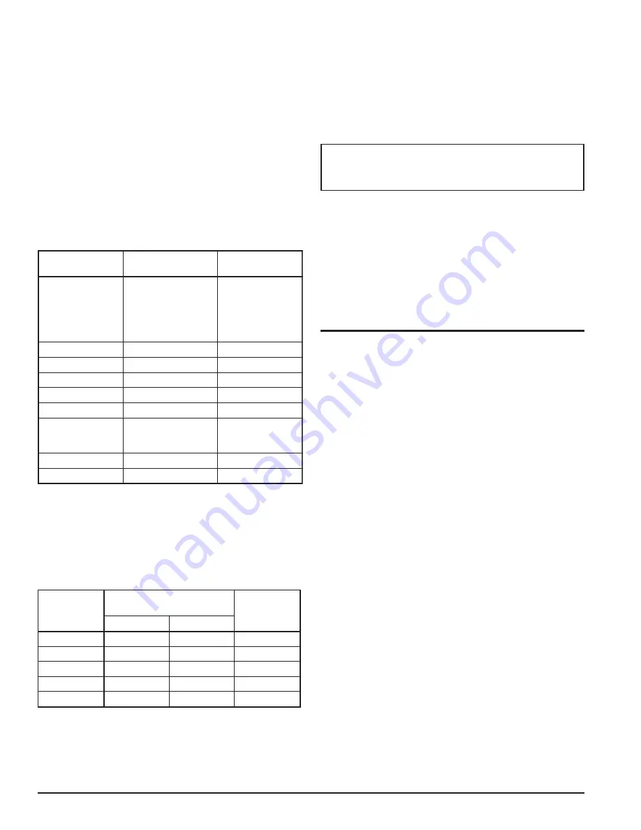
To ensure continued good operation and performance of
the dryer cooling system, the recommended ranges for dif-
ferent water constituents are shown in Table III.

Table III

Water Quality Requirements

R

E

T

E

M

A

R

A

P

N

O

I

T

A

R

T

N

E

C

N

O

C

F

O

Y

C

N

E

U

Q

E

R

F

S

I

S

Y

L

A

N

A

y

ti

v

i

s

o

rr

o

C

,

H

p

,

s

s

e

n

d

r

a

H

(

d

e

v

l

o

s

s

i

d

l

a

t

o

t

,

s

d

il

o

s

t

a

e

r

u

t

a

r

e

p

m

e

t

)

y

ti

n

il

a

k

l

a

,t

e

l

n

i

x

e

d

n

I

r

e

il

e

g

n

a

L

1

o

t

0

y

l

h

t

n

o

M

4

o

t

3

r

o

f

e

l

b

a

t

s

fI

e

z

y

l

a

n

a

,

s

h

t

n

o

m

y

lr

e

tr

a

u

q

n

o

rI

m

p

p

2

<

y

l

h

t

n

o

M

e

t

a

fl

u

S

m

p

p

0

5

<

y

l

h

t

n

o

M

e

d

ir

o

l

h

C

m

p

p

0

5

<

y

l

h

t

n

o

M

e

t

a

rt

i

N

m

p

p

2

<

y

l

h

t

n

o

M

a

c

ili

S

m

p

p

0

0

1

<

y

l

h

t

n

o

M

n

e

g

y

x

o

d

e

v

l

o

s

s

i

D

m

p

p

0

)

e

l

b

i

s

s

o

p

s

a

w

o

l

s

a

(

y

li

a

D

l

a

r

e

v

e

s

r

o

f

e

l

b

a

t

s

fI

y

l

k

e

e

w

e

z

y

l

a

n

a

,

s

y

a

d

e

s

a

e

r

g

d

n

a

li

O

m

p

p

5

<

y

l

h

t

n

o

M

a

i

n

o

m

m

A

m

p

p

1

<

y

l

h

t

n

o

M

Air-Cooled Models

Cooling air must be drawn from a clean source to reduce
dust and dirt accumulation on the condenser coils. Air tem-
perature (refer to Table IV) should not exceed 100°F.

Table IV

COOLING AIR REQUIREMENTS

R

E

Y

R

D

L

E

D

O

M

G

N

I

T

A

R

R

E

W

O

P

r

o

t

o

M

n

a

F

G

N

I

L

O

O

C

W

O

L

F

R

I

A

¹

)

m

f

c

(

y

t

Q

)

h

c

a

e

(

p

h

0

0

2

1

8

/

1

0

0

8

,

1

0

0

3

1

4

/

1

0

0

8

,

1

0

0

4

1

3

/

1

0

0

2

,

2

0

0

5

1

3

/

1

5

7

3

,

2

0

0

6

1

3

/

1

0

0

2

,

2

1

Air flows listed represent unrestricted air flow.

Electrical Installation

The dryer data plate lists the electric power requirements
for the dryer.

Confirm that your line voltage is the same as the voltage
listed on the data plate. Provide disconnect and fuses in
accordance with applicable codes. Field wiring must com-
ply with local and national fire, safety and electrical codes.

CAUTION

Operation of dryers with improper line voltage con-
stitutes abuse and could affect the dryer warranty.

Standard dryer enclosures and controls are designed to
meet NEMA Type 1 electrical standards. All wiring is com-
plete. Connect power leads as indicated in electrical sche-
matic and marked in the electrical enclosure. Ground the
frame.

Install a branch circuit disconnect in accordance with the
National Electrical Code and local standards. The discon-
nect must be adequate to handle the starting current.

HOW IT WORKS

Airflow

Energy Saving Cycling dryers use refrigeration cooling to
condense entrained moisture out of the airstream. Warm
saturated air enters an air-to-air heat exchanger, where it
is cooled by outgoing cold air. The inlet air is further cooled
in the glycol chiller (air-to-glycol solution heat exchanger).
Cooling condenses entrained moisture.

The condensate is removed from the airstream by a grav-
ity separator and discharged from the dryer by an auto-
matic drain valve.

The cold air is reheated by incoming warm air as it passes
back through the air-to-air heat exchanger. Using the out-
going air to pre-cool the inlet air condenses up to 65 per-
cent of the moisture out of the inlet air before it reaches the
chiller. Pre-cooling the inlet air reduces the heat load on
the refrigerant compressor, permitting the use of a smaller
refrigerant compressor.

Refrigeration System

The refrigeration system is designed and fabricated in ac-
cordance with recognized commercial/industrial practices.
It consists of a compressor, a compressor motor contactor
and the controls, safety interlocks and associated equip-
ment necessary for safe performance.

A high discharge pressure switch interlocked with the mo-
tor-compressor contactor turns the refrigerant compressor
off if cooling is inadequate. This switch prevents damage
to the compressor and must be manually reset.

Summary of Contents for RCD Series

Page 1: ...ESSED AIR DRYERS INSTRUCTION MANUAL Models RCD 200 through RCD 600 E N G L I S H 8610 483 9 Rev A 03 04 Bulletin 18 2 685 2nd Edition 5030C 040313 INTERNAL USE ONLY E N G L I S H INTERNAL USE ONLY E N...

Page 2: ...uling 1 4 Air Cooled Models 1 4 Electrical Installation 1 4 HOW IT WORKS 1 4 Airflow 1 4 Refrigeration System 1 4 ENERGY MANAGEMENT CONTROLLER EMC 1 6 Controller Operation 1 6 Dryer Warmup 1 6 EMC MEM...

Page 3: ...evere in jury or death 4 High voltage in the motor and control box is danger ous The dryer must be installed in accordance with recognized electrical codes Before working on the elec trical system dis...

Page 4: ...our responsibility Handling The dryer is mounted on a base to facilitate moving the dryer with a forklift Forks should extend all the way through the forklift channels provided to reduce stress on the...

Page 5: ...n Table II will cause a rise in dew point unless the dryer inlet air flow is reduced The refrigerant discharge pressure control will shut down the refrigerant compressor if cooling water is inadequate...

Page 6: ...the dryer Confirm that your line voltage is the same as the voltage listed on the data plate Provide disconnect and fuses in accordance with applicable codes Field wiring must com ply with local and...

Page 7: ...PROCESS PORT HIGH SIDE PROCESS PORT CAPILLARY TUBES DISTRIBUTOR AIRFLOW ASSEMBLY OUTLET AIR INLET AIR HPS T Figure 1 Flow Schematic Air Cooled Models CONDENSER AMBIENT AIRFLOW HIGH PRESSURE CUT OUT S...

Page 8: ...ee table below so that the crankcase heater has sufficient time to warm up before starting Warmup Delay Times e m i T f f O r e w o P e m i T y a l e D r e y r D e t u n i m 1 o t 0 s d n o c e s 0 6...

Page 9: ...nctions and starts the dryer i e the Dryer On LED lights STOP Button Push button that deactivates the controller and stops the dryer i e the Dryer On LED is off Up and Down Buttons Used to change the...

Page 10: ...k on The LED will stay lit until the STOP button is pushed Dryer On LED Indicates the dryer is on This light will blink if the START button is pressed during the compressor warm up period Left hand Co...

Page 11: ...value in memory Note All changes will be lost if you do not press the SET button before moving to another display param eter i e pressing the DISPLAY SELECT button Set Auto Drain Off Time Min LED Indi...

Page 12: ...ryer down The ADV has two LED indicators and a test button to help verify operation Pushing the test button causes the drain port to click open One LED indicates that power is sup plied to the ADV the...

Page 13: ...5 Slowly open the customer supplied blowdown inter nal pressure relief valve to vent the internal pressure 6 Close the blowdown valve when internal pressure is 0 psig DANGER Portions of the control c...

Page 14: ...ket from the solenoid coil housing Do not damage or lose the gasket 6 Remove 13mm nut and spring washer from top of so lenoid coil housing 7 Lift solenoid coil housing off solenoid core in valve body...

Page 15: ...e L e g r a h e r d n a r i a p e r k a e l e t a c o L n o i t a r e g i r f e r n i s e l b a s n e d n o c n o n r o r i A r e l l i h c n i k a e l e l b i s s o P m e t s y s e b t s u m r e l l...

Page 16: ...Type Valve Aids in Disconnecting Compressor from the System PRESSURE GUAGE THERMOMETER DRIP LEG MANOMETER DIFFERENTIAL PRESSURE INDICATOR AUTOMATIC DRAIN VALVE FALSE LOADER Blows Off Air Outside of Co...

Page 17: ...5 8 3 4 4 4 1 4 8 6 5 4 6 3 1 2 7 3 5 0 6 2 2 2 0 1 5 5 4 1 9 7 1 3 6 4 0 4 0 1 0 0 3 3 7 8 1 5 7 3 7 2 2 0 1 5 2 0 4 8 7 9 5 8 3 4 4 4 1 4 8 6 5 4 6 3 1 2 7 3 5 0 6 2 2 2 0 1 5 5 4 1 9 7 1 8 7 4 7 6...

Page 18: ...5 6 5 4 e g a t l o V l a n i m o N 0 6 1 0 3 2 8 0 2 e g a t l o V n i M x a M 7 8 1 3 5 2 s p m A d a o L d e t a R 9 0 1 3 0 6 1 9 9 6 1 3 2 9 1 9 7 1 2 s p m A r o t o R d e k c o L 3 9 4 1 8 4 8...

Page 19: ...A 1 REPLACEMENT PARTS WIRING SCHEMATICS...

Page 20: ...A 2 REPLACEMENT PARTS Air Cooled Models 200 600 scfm 9 5 6 8 LEFT VIEW 7 4 TOP VIEW REAR VIEW FRONT VIEW 1 3 2...

Page 21: ...3 8 0 3 G 9 5 0 8 4 0 3 G 4 0 5 9 9 0 3 G 4 0 5 9 9 0 3 G 4 0 5 9 9 0 3 G r o t i c a p a C n u R r o t o M n a F 1 9 0 1 5 0 3 G 1 9 0 1 5 0 3 G 8 5 9 2 6 0 3 G 8 5 9 2 6 0 3 G 8 5 9 2 6 0 3 G 6 0 6...

Page 22: ...A 4 REPLACEMENT PARTS Water Cooled Models 200 600 scfm 10 7 9 LEFT VIEW 6 8 5 4 TOP VIEW REAR VIEW FRONT VIEW 1 3 2...

Page 23: ...C r o s s e r p m o C 9 2 6 6 3 1 3 G 9 2 6 6 3 1 3 G 9 2 6 6 3 1 3 G 9 2 6 6 3 1 3 G 9 2 6 6 3 1 3 G n o i t p O 3 E 0 6 0 3 2 8 0 2 r o s s e r p m o C 7 5 1 7 6 0 3 G 1 5 8 5 8 0 3 G 2 1 4 0 9 0 3...

Page 24: ...COMPRESSOR FAN 1 2 3 M 1S 28 29 30 EMERGENCY STOP SWITCH HIGH PRESSURE CUT OUT WITH MANUAL RESET HPS 32 27 26 25 J3 KEYBOARD MEMBRANE CONTROLLER ASSEMBLY MCA 8 1 CUTOUT SW COMPRESSOR DRAIN VALVE J6 J...

Page 25: ...TOP SWITCH GND COMPRESSOR FAN 1 2 3 HIGH PRESSURE CUT OUT WITH MANUAL RESET J3 KEYBOARD 1 MEMBRANE CONTROLLER ASSEMBLY MCA 1S DRAIN VALVE 26 25 1SOL 24 23 22 NO COM NC ALARM CONTACTS NO NC UNPOWERED R...

Page 26: ...DRAIN VALVE GND EMERGENCY STOP SWITCH COMPRESSOR FAN 1 2 3 31 M 32 1S HPS HIGH PRESSURE CUT OUT WITH MANUAL RESET 24 23 22 NC COM NO 2TS ALARM CONTACTS NO NC UNPOWERED RATING 5A 115 VAC 5A 24 VDC CHA...

Page 27: ...ECTIONS HERE POP RIVET 3 16 BRACKET INSERT BRACKET TM E6X CONDUIT SEALING RING 1 2 WASHER LOCK PLATED 5 16 WASHER FLAT PLATED 1 4 NUT HEX PLATED 1 4 20 BOLT HEX HEAD PLATED 1 4 20 x 0 5 LG WASHER LOCK...

Page 28: ......

Page 29: ...a l p s i D e t a D e m i T y B n i a r D o t u A e v l a V l i O p m o C l e v e L n O r e w o P h g i H e r u t a r e p m e T m r a l A w o L e r u t a r e p m e T m r a l A s s e c o r P s l o r t...

Page 30: ...a l p s i D e t a D e m i T y B n i a r D o t u A e v l a V l i O p m o C l e v e L n O r e w o P h g i H e r u t a r e p m e T m r a l A w o L e r u t a r e p m e T m r a l A s s e c o r P s l o r t...

Page 31: ......

Page 32: ...D IS EXPRESSLY IN LIEU OF THE IMPLIED WARRANTY OF MERCHANTABILITY AND THE IMPLIED WARRANTY OF FITNESS FOR A PARTICULAR PURPOSE THE MANUFACTURER SHALL NOT BE LIABLE FOR LOSS OR DAMAGE BY REASON OF STRI...

Reviews: