


SB--7--622 Page 19
FIGURE 19
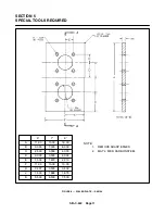
FIGURE 20
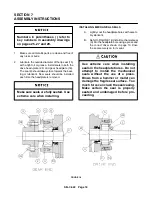
3.
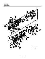
Assemble gear headplate (18) and mounting foot
(17) to the impeller case with cap screws (21) and
where the mounting foot is secured to the head-
plate use capscrews (16). The two positioning
dowel pins (19) will ensure proper alignment of the
headplate and impeller case. Also secure lifting
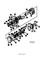
lugs using capscrews (21) (see exploded assem-
bly drawing page 25). Torque capscrews alter-
nately and evenly. Refer to FIGURE 24, page 24,
for torque specifications.
4.
Apply a light oil or grease on the shaft seal areas
and the bearing areas. Insert impellers into the
gear headplate using the same headplate bores
as used in the original assembly.
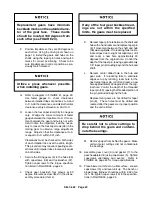
Seals are delicate; use extreme care
when installing impeller shafts in the
headplate bores. A piece of light shim
stock wrapped around the shaft key-
way will prevent cutting the seal lip.
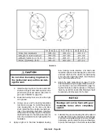
5.
Position blower so that impellers are vertical, with
the drive end on top. It will be necessary to use
blocks in order for the unit to set level. Measure
the total end clearance using a depth micrometer
(see FIGURE 19).
If total clearance is not within the limits specified
in FIGURE 21, page 20, it may be necessary to
shim the case to obtain the proper total end clear-
ance. The shim should be placed between the
drive headplate and impeller case.
If more than .007” shim is required,
put .007” on the drive end and the
remaining on the gear end.
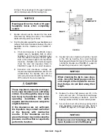
6.
Assemble drive headplate (24) to impeller case as
done in step 3 with the gear headplate. If shims
were required, place shims between drive head-
plate and impeller case.
7.
Insert bearing--seal spacers (34), (41) into the
drive shaft headplate bore and spacer (33) into the
remaining bores (see exploded view, page 25).
MECHANICAL SEALS ONLY
A. Refer to FIGURE 18, page18. Lightly coat
the impeller shaft (H) and the inside diameter
of the mating ring (B) with assembly
lubricant.
B. Install the mating ring (B) on the shaft only far
enough to install spacer (34), (41) in the bore
and allow for the bearing inner race (E) to be
started on the shaft.
Summary of Contents for LEGEND GAF P Series
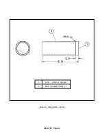
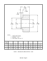
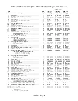
Page 19: ...SB 7 622 Page 12 1 PIPE STEEL 2 SCH 80 2 MED CARBON STEEL 1 2 FIGURE 9 GEAR DRIVER SK2150...
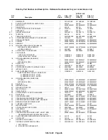
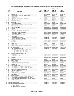
Page 32: ...SB 7 622 Page 25 SECTION 8 PARTS LIST 300GAF810 B Ref Drawing...
Page 34: ...SB 7 622 Page 27 300GAG810 A Ref Drawing...
Page 36: ...SB 7 622 Page 29 300GAH810 A Ref Drawing...
Page 39: ......


