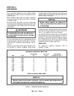


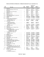
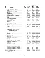

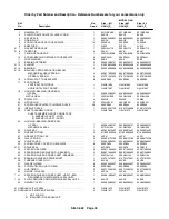

SB--7--622 Page 22
16.
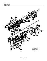
SETTING IMPELLER END CLEARANCE
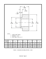
Refer to FIGURE 18, page 18. The gear end
bearings are held in position by the force created
by the wavy spring (28) on the drive end and the
bearing retainer (12) on the gear end. The inter-
ference fit between the shaft (H) and the bearing
inner race (E) keeps the shaft from moving axially.
End clearance adjustment of both impellers is
controlled by adjustment of the bearing retainer
(12). Tightening the bearing retainer screws (10)
moves the bearing to load the wavy spring (28),
and the impeller is forced toward the drive end.
Relaxing the screws allows the wavy spring to re-
turn the impeller toward the gear end.
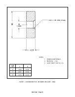
A. With impellers tight against the gear head-
plate, measure the distance (A) from the
bearing outer race to the gear headplate us-
ing a depth micrometer (see FIGURE 22,
page 21.
B. Subtract 1/3 of the total end clearance from
the value measured at point A. This value is
the amount of shim (13) that should be
placed between the retainer and the head-
plate at point (S).
C. Secure bearing retainer (12) with the correct
amount of shim, to the headplate using
capscrews (10). Torque capscrews to the
specifications given in FIGURE 24, page 24.
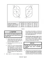
D. Recheck end clearances. Approximately 1/3
of the total end clearance should be on the
gear end and the remaining 2/3 on the drive
end (refer to FIGURE 21, page 20).
If clearances require adjusting, loosen the bearing
retainer capscrews (10) and insert shims to move
the impeller closer to the gear headplate and
remove shims to move the impellers away from
the gear headplate.
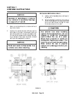
17.
INSTALLING THE TIMING GEARS
Impellers are held in time by gears which are taper
pinned and bolted to a timing hub, which in turn is
pressed and taper pinned onto the shaft. The
timing gears can be rotated in relation to the hub
by removing the taper pins in the web of the gear
and loosening the capscrews. Because the cap-
screws are oversized, the gear will rotate -- within
limits -- relative to the timing hub when the screws
are loosened.
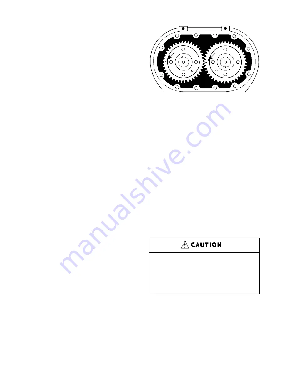
FIGURE 23
A. Apply a light grease, or oil, on the shaft area
where the timing gear will be positioned.
B. Lubricate the inside diameter of spacers (32)
with assembly lubricant and install on the
gear end shafts.
C. Using a piece of paper large enough to cover
the open end of the gear headplate, trace the
shafts on the paper and cut-out shaft holes.
This will be placed on the shafts before the
gears to protect the bearings from metal
shavings when drilling taper pin holes in the
following procedure.
D. Place feeler stock in the amount of 1/3 of the
total end clearance between drive headplate
and both impellers. This will stop the impel-
lers from contacting the headplate while the
gears are being driven on.
If installing gears on a blower
containing mechanical seals, a press
must be used to drive the gears on the
shafts.
Blows from a hammer or
mallet will damage the seal.
E. If reusing the timing gears and hubs, they
should be returned to their original position
with respect to the impellers.
If replacement gears are used, secure each
gear (9) to its timing hub (39) with capscrews
(38) and lockwasher (37) and tighten slightly.
Summary of Contents for LEGEND GAF P Series
Page 19: ...SB 7 622 Page 12 1 PIPE STEEL 2 SCH 80 2 MED CARBON STEEL 1 2 FIGURE 9 GEAR DRIVER SK2150...
Page 32: ...SB 7 622 Page 25 SECTION 8 PARTS LIST 300GAF810 B Ref Drawing...
Page 34: ...SB 7 622 Page 27 300GAG810 A Ref Drawing...
Page 36: ...SB 7 622 Page 29 300GAH810 A Ref Drawing...
Page 39: ......


